- 您現(xiàn)在的位置:買賣IC網(wǎng) > PDF目錄379094 > CY7C43633 (Cypress Semiconductor Corp.) 512 x36 Unidirectional Synchronous FIFO w/ Bus Matching(512 x36 單向同步先進(jìn)先出帶總線匹配) PDF資料下載
參數(shù)資料
| 型號: | CY7C43633 |
| 廠商: | Cypress Semiconductor Corp. |
| 英文描述: | 512 x36 Unidirectional Synchronous FIFO w/ Bus Matching(512 x36 單向同步先進(jìn)先出帶總線匹配) |
| 中文描述: | 512 x36單向同步FIFO瓦特/總線匹配(512 x36單向同步先進(jìn)先出帶總線匹配) |
| 文件頁數(shù): | 3/28頁 |
| 文件大小: | 422K |
| 代理商: | CY7C43633 |
第1頁第2頁當(dāng)前第3頁第4頁第5頁第6頁第7頁第8頁第9頁第10頁第11頁第12頁第13頁第14頁第15頁第16頁第17頁第18頁第19頁第20頁第21頁第22頁第23頁第24頁第25頁第26頁第27頁第28頁
CY7C43623
CY7C43633/CY7C43643
CY7C43663
/
CY7C43683
3
PRELIMINARY
Functional Description
The CY7C436x3 is a monolithic, high-speed, low-power,
CMOS Unidirectional Synchronous (clocked) FIFO memory
which supports clock frequencies up to 133 MHz and has read
access times as fast as 6 ns. Two independent 256/512/1K/4K/
16K x 36 dual-port SRAM FIFOs on board each chip buffer
data in opposite directions. FIFO data on Port B can be output
in 36-bit, 18-bit, or 9-bit formats with a choice of Big or Little
Endian configurations.
The CY7C436x3 is a synchronous (clocked) FIFO, meaning
each port employs a synchronous interface. All data transfers
through a port are gated to the LOW-to-HIGH transition of a
port clock by enable signals. The clocks for each port are in-
dependent of one another and can be asynchronous or coin-
cident. The enables for each port are arranged to provide a
simple unidirectional interface between microprocessors and/
or buses with synchronous control.
Communication between each port may bypass the FIFOs via
two mailbox registers. The mailbox registers
’
width matches
the selected Port B bus width. Each mailbox register has a flag
(MBF1 and MBF2) to signal when new mail has been stored.
Two kinds of reset are available on the CY7C436x3: Master
Reset and Partial Reset. Master Reset initializes the read and
write pointers to the first location of the memory array, config-
ures the FIFO for Big or Little Endian byte arrangement and
selects serial flag programming, parallel flag programming, or
one of the three possible default flag offset settings, 8, 16, or
64. The FIFO also has two Master Reset pins, MRS1 and
MRS2.
Partial Reset also sets the read and write pointers to the first
location of the memory. Unlike Master Reset, any settings ex-
isting prior to Partial Reset (i.e., programming method and par-
tial flag default offsets) are retained. Partial Reset is useful
since it permits flushing of the FIFO memory without changing
any configuration settings. The FIFO has its own independent
Partial Reset pin, PRS.
The CY7C436x3 have two modes of operation: In the CY Stan-
dard Mode, the first word written to an empty FIFO is deposited
into the memory array. A read operation is required to access
that word (along with all other words residing in memory). In
the First-Word Fall-Through Mode
(FWFT), the first long-word
(36-bit wide) written to an empty FIFO appears automatically
on the outputs, no read operation required (nevertheless, ac-
cessing subsequent words does necessitate a formal read re-
quest). The state of the BE/FWFT pin during FIFO operation
determines the mode in use.
The FIFO has a combined Empty/Output Ready flag (EF/OR)
and a combined Full/Input Ready flag (FF/IR). The EF and FF
functions are selected in the CY Standard Mode. EF indicates
whether the memory is full or not. The IR and OR functions are
selected in the First-Word Fall-Through Mode. IR indicates
whether or not the FIFO has available memory locations. OR
shows whether the FIFO has data available for reading or not.
It marks the presence of valid data on the outputs.
The FIFO has a programmable Almost Empty flag (AE) and a
programmable Almost Full flag (AF). AE indicates when a se-
lected number of words written to FIFO memory achieve a
predetermined
“
almost empty state.
”
AF indicates when a se-
lected number of words written to the memory achieve a pre-
determined
“
almost full state.
”
IR and AF are synchronized to the port clock that writes data
into its array. OR and AE are synchronized to the port clock
that reads data from its array. Programmable offset for AE and
AF are loaded in parallel using Port A or in serial via the SD
input. Three default offset settings are also provided. The AE
threshold can be set at 8, 16, or 64 locations from the empty
boundary and AF threshold can be set at 8, 16, or 64 locations
from the full boundary. All these choices are made using the
FS0 and FS1 inputs during Master Reset.
Two or more devices may be used in parallel to create wider
data paths. If any time the FIFO is not actively performing a
function, the chip will automatically power down. During the
power-down state, supply current consumption (I
CC
) is at a
minimum. Initiating any operation (by activating control inputs)
will immediately take the device out of the power-down state.
The CY7C436x3 are characterized for operation from 0
°
C to
70
°
C. Input ESD protection is greater than 2001V, and latch-
up is prevented by the use of guard rings.
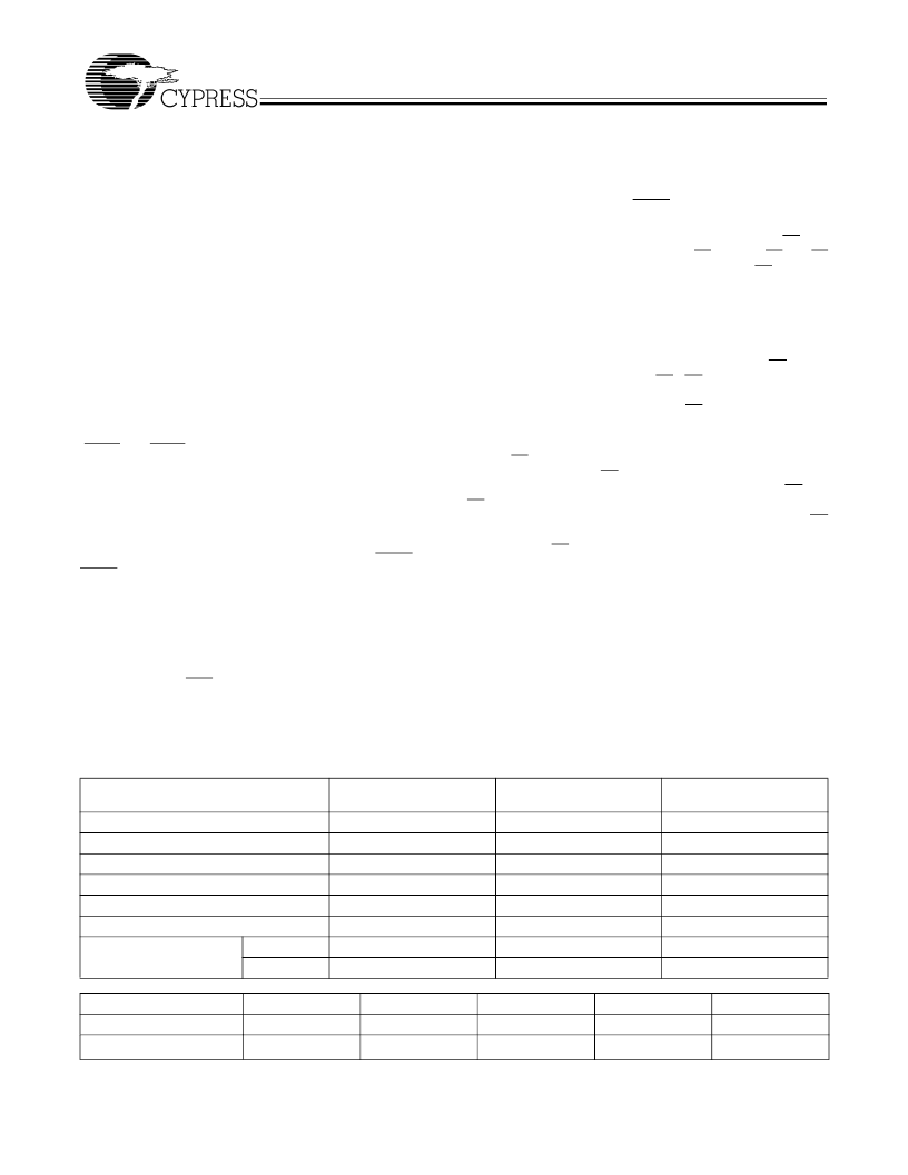
Selection Guide
CY7C43623/33/43/63/83
–
7
133
6
7.5
3
0
8
100
CY7C43623/33/43/63/83
–
10
100
8
10
4
0
8
100
CY7C43623/33/43/63/83
–
15
66.7
10
15
5
0
8
100
100
Maximum Frequency (MHz)
Maximum Access Time (ns)
Minimum Cycle Time (ns)
Minimum Data or Enable Set-Up (ns)
Minimum Data or Enable Hold (ns)
Maximum Flag Delay (ns)
Active Power Supply
Current (I
CC1
) (mA)
Commercial
Industrial
CY7C43623
256 x 36
128 TQFP
CY7C43633
512 x 36
128 TQFP
CY7C43643
1K x 36
128 TQFP
CY7C43663
4K x 36
128 TQFP
CY7C43683
16K x 36
128 TQFP
Density
Package
相關(guān)PDF資料 |
PDF描述 |
|---|---|
| CY7C43623 | 256 x36 Unidirectional Synchronous FIFO w/ Bus Matching(256 x36 單向同步先進(jìn)先出帶總線匹配) |
| CY7C43643 | 1K x36 Unidirectional Synchronous FIFO w/ Bus Matching(1K x36 單向同步先進(jìn)先出帶總線匹配) |
| CY7C43663 | 4K x36 Unidirectional Synchronous FIFO w/ Bus Matching(4K x36 單向同步先進(jìn)先出帶總線匹配) |
| CY7C43683 | 16K x36 Unidirectional Synchronous FIFO w/ Bus Matching(16K x36 單向同步先進(jìn)先出帶總線匹配) |
| CY7C43634 | 512 x36 x2 Bidirectional Synchronous FIFO w/ Bus Matching(512 x36 x2 雙向同步先進(jìn)先出 帶總線匹配) |
相關(guān)代理商/技術(shù)參數(shù) |
參數(shù)描述 |
|---|---|
| CY7C43642-10AC | 制造商:Cypress Semiconductor 功能描述:FIFO Mem Sync Dual Depth/Width Bi-Dir 1K x 36 x 2 120-Pin TQFP |
| CY7C43643-15AC | 制造商:Cypress Semiconductor 功能描述:FIFO Mem Sync Dual Depth/Width Uni-Dir 1K x 36 128-Pin TQFP 制造商:Rochester Electronics LLC 功能描述:- Bulk |
| CY7C43643AV-10AC | 制造商:Cypress Semiconductor 功能描述:FIFO Mem Sync Dual Depth/Width Uni-Dir 1K x 36 128-Pin TQFP |
| CY7C43643AV-15AC | 制造商:Cypress Semiconductor 功能描述:FIFO Mem Sync Dual Depth/Width Uni-Dir 1K x 36 128-Pin TQFP |
| CY7C43643AV-7AC | 制造商:Cypress Semiconductor 功能描述:FIFO Mem Sync Dual Depth/Width Uni-Dir 1K x 36 128-Pin TQFP |
發(fā)布緊急采購,3分鐘左右您將得到回復(fù)。