- 您現(xiàn)在的位置:買賣IC網(wǎng) > PDF目錄210357 > BUS-65164-110S (DATA DEVICE CORP) 2 CHANNEL(S), 1M bps, MIL-STD-1553 CONTROLLER, CDFP70 PDF資料下載
參數(shù)資料
| 型號(hào): | BUS-65164-110S |
| 廠商: | DATA DEVICE CORP |
| 元件分類: | 微控制器/微處理器 |
| 英文描述: | 2 CHANNEL(S), 1M bps, MIL-STD-1553 CONTROLLER, CDFP70 |
| 封裝: | 1.900 X 1 INCH, 0.215 INCH HEIGHT, FP-70 |
| 文件頁(yè)數(shù): | 26/40頁(yè) |
| 文件大小: | 349K |
| 代理商: | BUS-65164-110S |
第1頁(yè)第2頁(yè)第3頁(yè)第4頁(yè)第5頁(yè)第6頁(yè)第7頁(yè)第8頁(yè)第9頁(yè)第10頁(yè)第11頁(yè)第12頁(yè)第13頁(yè)第14頁(yè)第15頁(yè)第16頁(yè)第17頁(yè)第18頁(yè)第19頁(yè)第20頁(yè)第21頁(yè)第22頁(yè)第23頁(yè)第24頁(yè)第25頁(yè)當(dāng)前第26頁(yè)第27頁(yè)第28頁(yè)第29頁(yè)第30頁(yè)第31頁(yè)第32頁(yè)第33頁(yè)第34頁(yè)第35頁(yè)第36頁(yè)第37頁(yè)第38頁(yè)第39頁(yè)第40頁(yè)
P.C. BOARD LAYOUT GUIDELINES
GROUND PLANES
As is the rule in all high speed digital circuits, it is good practice
to use ground and power supply planes under the STIC hybrid
as well as the associated components.
The reason for not using supply or ground planes under the ana-
log signal traces is that the effect of the distributed capacitance
will be to lower the input impedance of the terminal, as seen from
the 1553 bus. MIL-STD-1553 requires a minimum input imped-
ance of 2000 ohms for direct coupled terminals and 1000 ohms
for transformer (stub) coupled terminals. If there are ground
planes under the analog bus signal traces, it is likely that the ter-
minal will not meet this requirement.
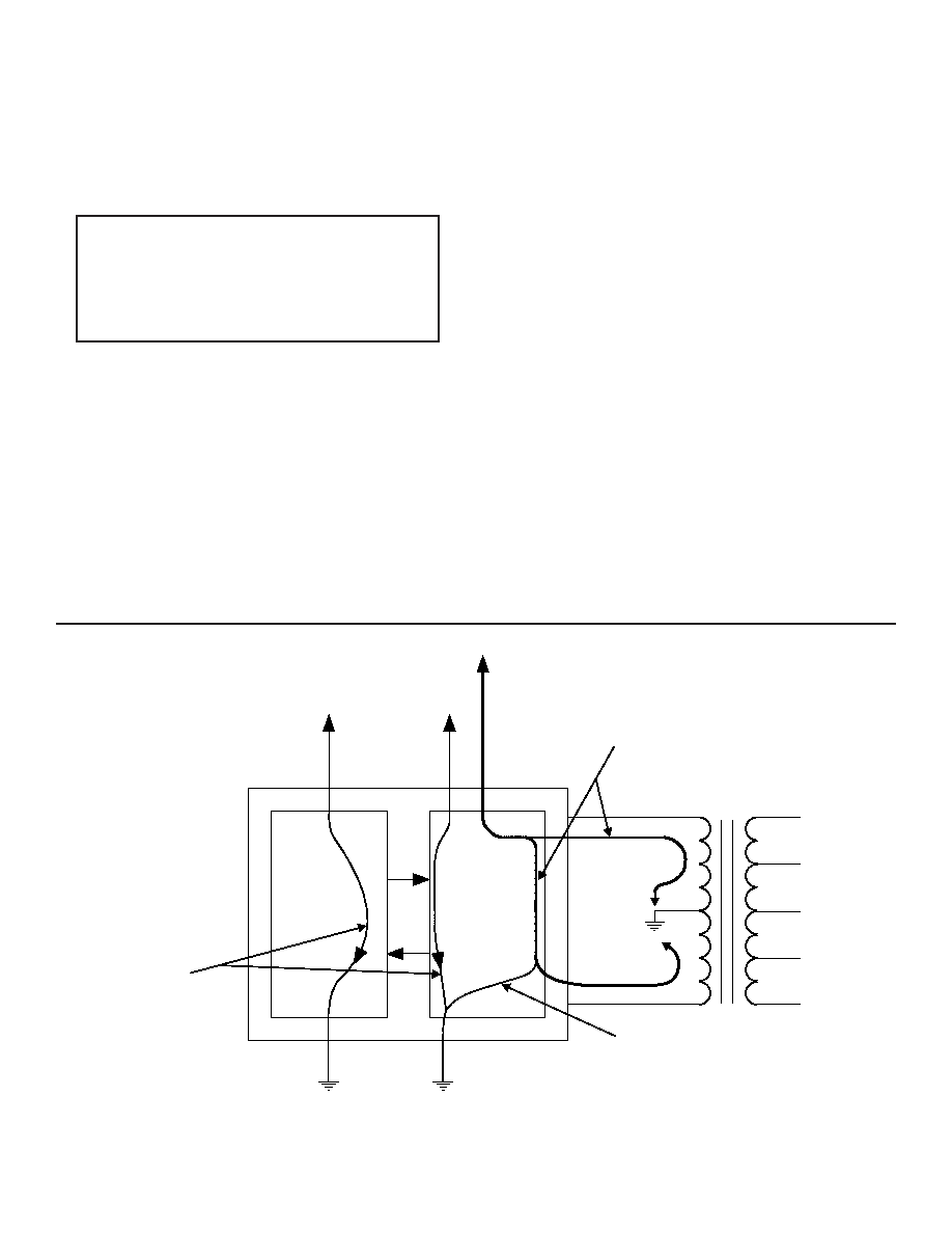
POWER AND GROUND DISTRIBUTION
Another important consideration is power and ground distribu-
tion. Refer to FIGURE 19. For the STIC hybrid/transformer com-
bination, the high current path when the STIC is transmitting will
be from the -15 volt power supply, through the transmitter output
stage, through one leg of the isolation transformer to the trans-
former center tap. It is important to realize that the high current
return path is through the transformer center tap and not
through the STIC's GND pin.
It is an important layout consideration to minimize the power
supply distribution impedance along this path. Any resistance
will result in voltage drops for the power supply input voltage,
and can ultimately lower the transmitter output voltage, possibly
below the minimum level required by MIL-STD-1553.
1553 BUS CONNECTIONS
The isolation transformers should be placed as physically
close as possible to the respective TX/RX pins on the STIC and
the distance from the isolation transformers to any connectors or
cables leaving the board should be as short as possible. In
addition to limiting the voltage drops in the analog signal traces
when transmitting, reducing the hybrid-to-transformer and trans-
former-to-connector spacings serves to minimize crosstalk from
other signals on the board.
The general practice in connecting the stub side of a transformer
(or direct) coupled terminal to an external system connector is to
make use of 78 ohm twisted-pair shielded cable. This minimizes
impedance discontinuities. The decision of whether to isolate or
make connections between the center tap of the isolation trans-
former's secondary, the stub shield, the bus shield, and/or chas-
sis ground must be made on a system basis, as determined by
an analysis of EMI/RFI and lightning considerations.
In most systems, it is specified that the 1553 terminal's input
impedance must be measured at the system connector. This is
32
FIGURE 19. POWER/GROUND CURRENT DISTRIBUTION
IT IS VERY IMPORTANT THAT THERE BE NO
GROUND AND/OR POWER SUPPLY PLANES UNDER-
NEATH ANY OF THE ANALOG BUS SIGNAL TRACES-
THIS APPLIES TO THE TX/RX SIGNALS RUNNING
FROM THE STIC HYBRID TO THE TRANSFORMERS
AS WELL AS FROM THE TRANSFORMERS TO ANY
CONNECTORS OR CABLES LEAVING THE BOARD
LOGIC
RX
TRANSCEIVER
TX
1
2
3
6
8
7
5
4
BUS-41429
HIGH LEVEL
CURRENTS
LOW LEVEL
CURRENTS
LOW LEVEL
CURRENTS
LOGIC
GND
GND A/B
+5 V
LOGIC
+5 V A/B
-15 V/-12 V (A/B)
BUS-29854
BUS-25679
相關(guān)PDF資料 |
PDF描述 |
|---|---|
| BUS-65164-130K | 2 CHANNEL(S), 1M bps, MIL-STD-1553 CONTROLLER, CDFP70 |
| BUS-65164-180K | 2 CHANNEL(S), 1M bps, MIL-STD-1553 CONTROLLER, CDFP70 |
| BU-61743F3-100W | 2 CHANNEL(S), 1M bps, MIL-STD-1553 CONTROLLER, CQFP72 |
| BU-61743F3-202L | 2 CHANNEL(S), 1M bps, MIL-STD-1553 CONTROLLER, CQFP72 |
| BU-61743F3-202W | 2 CHANNEL(S), 1M bps, MIL-STD-1553 CONTROLLER, CQFP72 |
相關(guān)代理商/技術(shù)參數(shù) |
參數(shù)描述 |
|---|---|
| BU-S802 | 制造商:Fuji Electric 功能描述: |
| BU-S803 | 制造商:Fuji Electric 功能描述: |
| BUS98 | 制造商:ONSEMI 制造商全稱:ON Semiconductor 功能描述:SITCHMODE Series NPN Silicon Power Transistors |
| BUS98/D | 制造商:未知廠家 制造商全稱:未知廠家 功能描述:SWITCHMODE? Series NPN Silicon Power Transistors |
| BUS98A | 制造商:ONSEMI 制造商全稱:ON Semiconductor 功能描述:SITCHMODE Series NPN Silicon Power Transistors |
發(fā)布緊急采購(gòu),3分鐘左右您將得到回復(fù)。