- 您現(xiàn)在的位置:買(mǎi)賣(mài)IC網(wǎng) > PDF目錄378405 > AP87C54-20 (INTEL CORP) CHMOS SINGLE-CHIP 8-BIT MICROCONTROLLER WITH 16 KBYTES USER PROGRAMMABLE EPROM PDF資料下載
參數(shù)資料
| 型號(hào): | AP87C54-20 |
| 廠商: | INTEL CORP |
| 元件分類: | 微控制器/微處理器 |
| 英文描述: | CHMOS SINGLE-CHIP 8-BIT MICROCONTROLLER WITH 16 KBYTES USER PROGRAMMABLE EPROM |
| 中文描述: | 8-BIT, OTPROM, 20 MHz, MICROCONTROLLER, PDIP40 |
| 封裝: | PLASTIC, DIP-40 |
| 文件頁(yè)數(shù): | 6/20頁(yè) |
| 文件大小: | 290K |
| 代理商: | AP87C54-20 |
第1頁(yè)第2頁(yè)第3頁(yè)第4頁(yè)第5頁(yè)當(dāng)前第6頁(yè)第7頁(yè)第8頁(yè)第9頁(yè)第10頁(yè)第11頁(yè)第12頁(yè)第13頁(yè)第14頁(yè)第15頁(yè)第16頁(yè)第17頁(yè)第18頁(yè)第19頁(yè)第20頁(yè)
AUTOMOTIVE 87C54/87C54-20
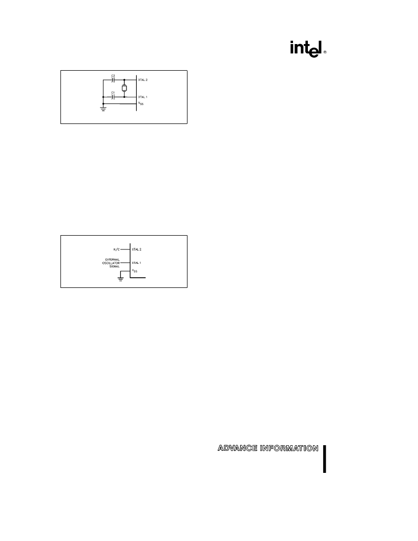
270849–5
C1, C2
e
30 pF
g
10 pF for Crystals
For Ceramic Resonators, contact resonator manufacturer.
Figure 4. Oscillator Connections
To drive the device from an external clock source,
XTAL1 should be driven, while XTAL2 floats, as
shown in Figure 5. There are no requirements on the
duty cycle of the external clock signal, since the in-
put to the internal clocking circuitry is through a di-
vide-by-two flip-flop, but minimum and maximum
high and low times specified on the data sheet must
be observed.
An external oscillator may encounter as much as a
100 pF load at XTAL1 when it starts up. This is due
to interaction between the amplifier and its feedback
capacitance. Once the external signal meets the V
IL
and V
IH
specifications the capacitance will not ex-
ceed 20 pF.
270849–6
Figure 5. External Clock Drive Configuration
IDLE MODE
The user’s software can invoke the Idle Mode. When
the microcontroller is in this mode, power consump-
tion is reduced. The Special Function Registers and
the onboard RAM retain their values during Idle, but
the processor stops executing instructions. Idle
Mode will be exited if the chip is reset or if an en-
abled interrupt occurs.
POWER DOWN MODE
To save even more power, a Power Down mode can
be invoked by software. In this mode, the oscillator
is stopped and the instruction that invoked Power
Down is the last instruction executed. The on-chip
RAM and Special Function Registers retain their val-
ues until the Power Down mode is terminated.
On the 87C54 either a hardware reset or an external
interrupt can cause an exit from Power Down. Reset
redefines all the SFRs but does not change the on-
chip RAM. An external interrupt allows both the
SFRs and on-chip RAM to retain their values.
To properly terminate Power down the reset or ex-
ternal interrupt should not be executed before V
CC
is
restored to its normal operating level and must be
held active long enough for the oscillator to restart
and stabilize (normally less than 10 ms).
With an external interrupt, INT0 or INT1 must be en-
abled and configured as level-sensitive. Holding the
pin low restarts the oscillator but bringing the pin
back high completes the exit. (The oscillator must be
allowed time to stabilize after start up, before this pin
is released high.) Once the interrupt is serviced, the
next instruction to be executed after RETI will be the
one following the instruction that put the device into
Power Down.
DESIGN CONSIDERATION
When the idle mode is terminated by a hardware
reset, the device normally resumes program execu-
tion, from where it left off, up to two machine cycles
before the internal reset algorithm takes control. On-
chip hardware inhibits access to internal RAM in this
event, but access to the port pins is not inhibited. To
eliminate the possibility of an unexpected write when
Idle is terminated by reset, the instruction following
the one that invokes Idle should not be one that
writes to a port pin or to external memory.
6
相關(guān)PDF資料 |
PDF描述 |
|---|---|
| Applications2SK3132 | Silicon N Channel MOS Type Chopper Regulator DC−DC Converter and Motor Drive Applications |
| APTM50DUM38TG | Dual common source MOSFET Power Module |
| APTM50H10FT3G | Full - Bridge MOSFET Power Module |
| APTM50H14FT3G | Full - Bridge MOSFET Power Module |
| APTM50HM38FG | Full - Bridge MOSFET Power Module |
相關(guān)代理商/技術(shù)參數(shù) |
參數(shù)描述 |
|---|---|
| AP8800 | 制造商:DIODES 制造商全稱:Diodes Incorporated 功能描述:350mA LED Step-Down Converter |
| AP-8800 | 制造商:GC Electronics 功能描述: 制造商:Winegard 功能描述: |
| AP8800_0912 | 制造商:DIODES 制造商全稱:Diodes Incorporated 功能描述:350mA LED Step-down Converter |
| AP8800A | 制造商:DIODES 制造商全稱:Diodes Incorporated 功能描述:COST EFFECTIVE 28V BUCK 1-W LED DRIVER |
| AP8800AWT-7 | 功能描述:LED照明驅(qū)動(dòng)器 28V 1-W LED Driver DC/DC Converter RoHS:否 制造商:STMicroelectronics 輸入電壓:11.5 V to 23 V 工作頻率: 最大電源電流:1.7 mA 輸出電流: 最大工作溫度: 安裝風(fēng)格:SMD/SMT 封裝 / 箱體:SO-16N |
發(fā)布緊急采購(gòu),3分鐘左右您將得到回復(fù)。