- 您現(xiàn)在的位置:買賣IC網(wǎng) > PDF目錄253907 > AM41PDS3224DB11FS (SPANSION LLC) SPECIALTY MEMORY CIRCUIT, PBGA73 PDF資料下載
參數(shù)資料
| 型號: | AM41PDS3224DB11FS |
| 廠商: | SPANSION LLC |
| 元件分類: | 存儲器 |
| 英文描述: | SPECIALTY MEMORY CIRCUIT, PBGA73 |
| 封裝: | 8 X 11.60 MM, FBGA-73 |
| 文件頁數(shù): | 11/59頁 |
| 文件大小: | 1072K |
| 代理商: | AM41PDS3224DB11FS |
第1頁第2頁第3頁第4頁第5頁第6頁第7頁第8頁第9頁第10頁當(dāng)前第11頁第12頁第13頁第14頁第15頁第16頁第17頁第18頁第19頁第20頁第21頁第22頁第23頁第24頁第25頁第26頁第27頁第28頁第29頁第30頁第31頁第32頁第33頁第34頁第35頁第36頁第37頁第38頁第39頁第40頁第41頁第42頁第43頁第44頁第45頁第46頁第47頁第48頁第49頁第50頁第51頁第52頁第53頁第54頁第55頁第56頁第57頁第58頁第59頁
18
Am41PDS3224D
May 13, 2002
P R E L IMINARY
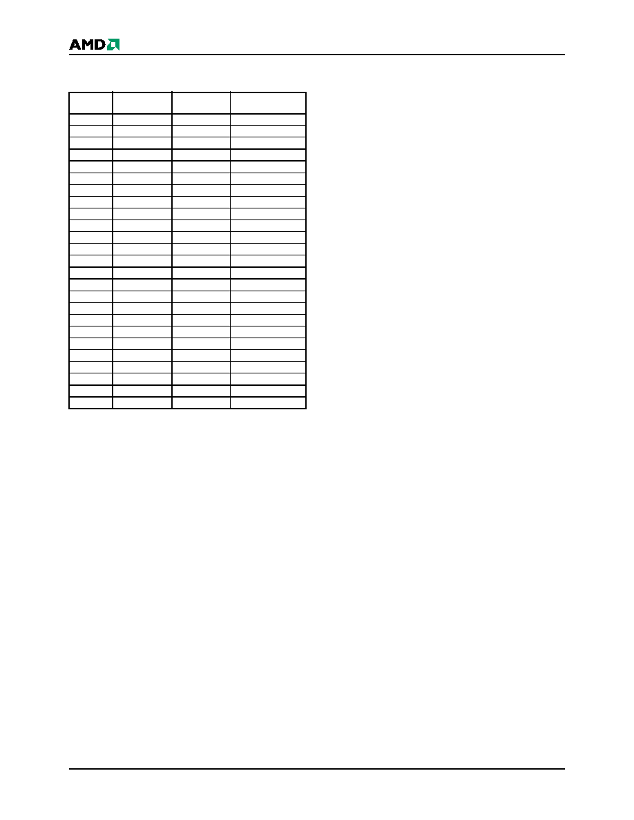
Table 9.
Bottom Boot Sector/Sector Block
Addresses for Protection/Unprotection
The hardware sector protection feature disables both
program and erase operations in any sector. The hard-
ware sector unprotection feature re-enables both
program and erase operations in previously protected
sectors.
Sector protection and unprotection requires V
ID on the
RESET# pin only, and can be implemented either
in-system or via programming equipment. Figure 2
shows the algorithms and Figure 26 shows the timing
diagram. This method uses standard microprocessor
bus cycle timing. For sector unprotect, all unprotected
sectors must first be protected prior to the first sector
unprotect write cycle.
The device is shipped with all sectors unprotected.
AMD offers the option of programming and protecting
sectors at its factory prior to shipping the device
through AMD’s ExpressFlash Service. Contact an
AMD representative for details.
It is possible to determine whether a sector is pro-
tected or unprotected. See the Autoselect Mode
section for details.
Write Protect (WP#)
The Write Protect function provides a hardware
method of protecting certain boot sectors without
using V
ID. This function is one of two provided by the
WP#/ACC pin.
If the system asserts V
IL on the WP#/ACC pin, the de-
vice disables program and erase functions in the two
“outermost” 8 Kbyte boot sectors independently of
whether those sectors were protected or unprotected
using the method described in “Sector/Sector Block
Protection and Unprotection”. The two outermost 8
Kbyte boot sectors are the two sectors containing the
lowest addresses in a top-boot-configured device, or
the two sectors containing the highest addresses in a
top-boot-configured device.
If the system asserts V
IH on the WP#/ACC pin, the de-
vice reverts to whether the two outermost 8 Kbyte boot
sectors were last set to be protected or unprotected.
That is, sector protection or unprotection for these two
sectors depends on whether they were last protected
or unprotected using the method described in “Sec-
Note that the WP#/ACC pin must not be left floating or
unconnected; inconsistent behavior of the device may
result.
Temporary Sector/Sector Block Unprotect
(Note: For the following discussion, the term “sector”
applies to both sectors and sector blocks. A sector
block consists of two or more adjacent sectors that are
protected or unprotected at the same time (see Table
8).
This feature allows temporary unprotection of previ-
ously protected sectors to change data in-system. The
Sector Unprotect mode is activated by setting the RE-
SET# pin to V
ID (9 V – 11 V ) . D u r ing this mo de,
formerly protected sectors can be programmed or
erased by selecting the sector addresses. Once V
ID is
removed from the RESET# pin, all the previously pro-
tected sectors are protected again. Figure 1 shows the
algorithm, and Figure 25 shows the timing diagrams,
for this feature.
Sector
Group
Sectors
A20–A12
Sector/Sector
Block Size
SGA0
SA70
111111XXX
64 (1x64) Kbytes
SGA1
SA69–SA67
11110XXXX
192 (3x64) Kbytes
SGA2
SA66–SA63
1110XXXXX
256 (4x64) Kbytes
SGA3
SA62–SA59
1101XXXXX
256 (4x64) Kbytes
SGA4
SA58–SA55
1100XXXXX
256 (4x64) Kbytes
SGA5
SA54–SA51
1011XXXXX
256 (4x64) Kbytes
SGA6
SA50–SA47
1010XXXXX
256 (4x64) Kbytes
SGA7
SA46–SA43
1001XXXXX
256 (4x64) Kbytes
SGA8
SA42–SA39
1000XXXXX
256 (4x64) Kbytes
SGA9
SA38–SA35
0111XXXXX
256 (4x64) Kbytes
SGA10
SA34–SA31
0110XXXXX
256 (4x64) Kbytes
SGA11
SA30–SA27
0101XXXXX
256 (4x64) Kbytes
SGA12
SA26–SA23
0100XXXXX
256 (4x64) Kbytes
SGA13
SA22–SA19
0011XXXXX
256 (4x64) Kbytes
SGA14
SA18–SA15
0010XXXXX
256 (4x64) Kbytes
SGA15
SA14–SA11
0001XXXXX
256 (4x64) Kbytes
SGA16
SA10–SA8
000011XXX
192 (3x64) Kbytes
SGA17
SA7
000000111
8 Kbytes
SGA18
SA6
000000110
8 Kbytes
SGA19
SA5
000000101
8 Kbytes
SGA20
SA4
000000100
8 Kbytes
SGA21
SA3
000000011
8 Kbytes
SGA22
SA2
000000010
8 Kbytes
SGA23
SA1
000000001
8 Kbytes
SGA24
SA0
000000000
8 Kbytes
相關(guān)PDF資料 |
PDF描述 |
|---|---|
| AM29F017D-120FD | 2M X 8 FLASH 5V PROM, 120 ns, PDSO48 |
| AM29LV004T-70RFF | 512K X 8 FLASH 3V PROM, 70 ns, PDSO40 |
| AM29LV004T-80EF | 512K X 8 FLASH 3V PROM, 80 ns, PDSO40 |
| AT28C1024-20BM/883 | 64K X 16 EEPROM 5V, 200 ns, CDIP40 |
| AM99C641-45/LMC | 64K X 1 STANDARD SRAM, 45 ns, CQCC22 |
相關(guān)代理商/技術(shù)參數(shù) |
參數(shù)描述 |
|---|---|
| AM41PDS3224DB11IS | 制造商:AMD 制造商全稱:Advanced Micro Devices 功能描述:32 Megabit (2 M x 16-Bit) CMOS 1.8 Volt-only, Simultaneous Operation, Page Mode Flash Memory and 4 Mbit (512 K x 8-Bit/256 K x 16-Bit) Static RAM |
| AM41PDS3224DB11IT | 制造商:AMD 制造商全稱:Advanced Micro Devices 功能描述:32 Megabit (2 M x 16-Bit) CMOS 1.8 Volt-only, Simultaneous Operation, Page Mode Flash Memory and 4 Mbit (512 K x 8-Bit/256 K x 16-Bit) Static RAM |
| AM41PDS3224DB35IS | 制造商:AMD 制造商全稱:Advanced Micro Devices 功能描述:32 Megabit (2 M x 16-Bit) CMOS 1.8 Volt-only, Simultaneous Operation, Page Mode Flash Memory and 4 Mbit (512 K x 8-Bit/256 K x 16-Bit) Static RAM |
| AM41PDS3224DB35IT | 制造商:AMD 制造商全稱:Advanced Micro Devices 功能描述:32 Megabit (2 M x 16-Bit) CMOS 1.8 Volt-only, Simultaneous Operation, Page Mode Flash Memory and 4 Mbit (512 K x 8-Bit/256 K x 16-Bit) Static RAM |
| AM41PDS3224DB40IS | 制造商:AMD 制造商全稱:Advanced Micro Devices 功能描述:32 Megabit (2 M x 16-Bit) CMOS 1.8 Volt-only, Simultaneous Operation, Page Mode Flash Memory and 4 Mbit (512 K x 8-Bit/256 K x 16-Bit) Static RAM |
發(fā)布緊急采購,3分鐘左右您將得到回復(fù)。