- 您現(xiàn)在的位置:買賣IC網(wǎng) > PDF目錄373868 > AD5100YRQZ-RL7 (ANALOG DEVICES INC) System-Management IC with Programmable Quad Voltage Monitoring and Supervisory Functions PDF資料下載
參數(shù)資料
| 型號(hào): | AD5100YRQZ-RL7 |
| 廠商: | ANALOG DEVICES INC |
| 元件分類: | 電源管理 |
| 英文描述: | System-Management IC with Programmable Quad Voltage Monitoring and Supervisory Functions |
| 中文描述: | 4-CHANNEL POWER SUPPLY MANAGEMENT CKT, PDSO16 |
| 封裝: | 0.025 INCH PITCH, ROHS COMPLIANT, MO-137AB, QSOP-16 |
| 文件頁數(shù): | 19/32頁 |
| 文件大小: | 495K |
| 代理商: | AD5100YRQZ-RL7 |
第1頁第2頁第3頁第4頁第5頁第6頁第7頁第8頁第9頁第10頁第11頁第12頁第13頁第14頁第15頁第16頁第17頁第18頁當(dāng)前第19頁第20頁第21頁第22頁第23頁第24頁第25頁第26頁第27頁第28頁第29頁第30頁第31頁第32頁
Preliminary Technical Data
AD5100
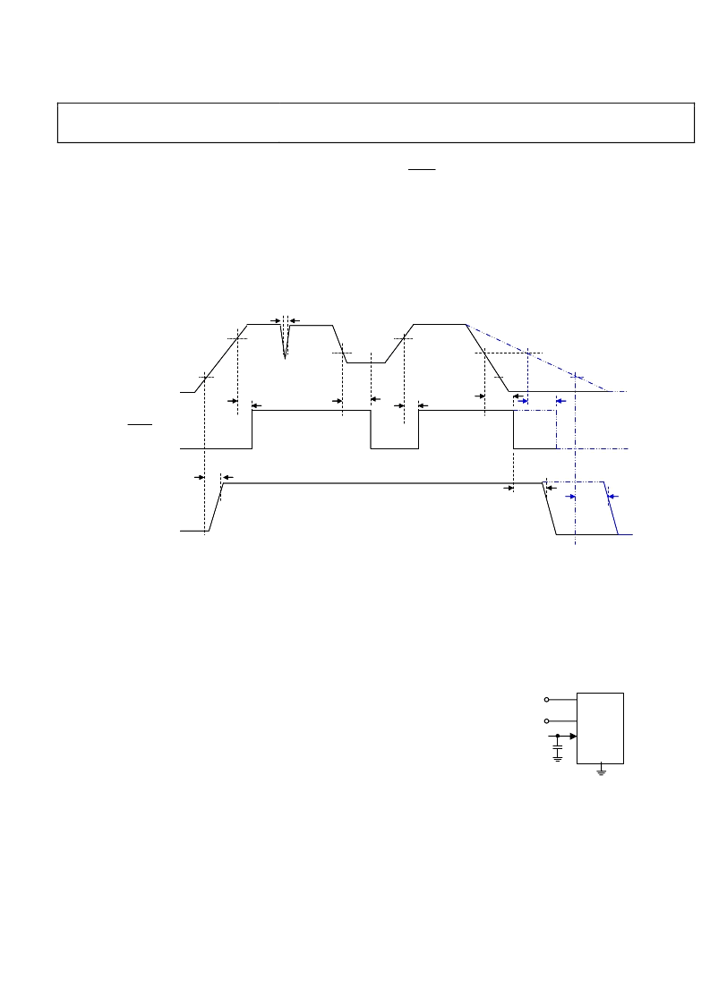
Power Requirements
Internal Power
The AD5100 internal power V
REG
is derived from V
1MON
and
V
2MON
is used to turn AD5100 on and off with a different
behavior depending on the V
2MON
monitoring mode
selection. By default, in the V
2MON
level sensitive mode, the
AD5100 turns on when the voltage at V
2MON
rises above the
logic threshold V
2MON_ON
, When V
2MON
falls below the logic
Rev. PrJ | Page 19 of 32
threshold V
2MON_OFF
, AD5100 will trun off 2 seconds after
SHDN
is deasserted. Note that AD5100 requries 5 us to start
up and that
V
1MON
must be applied before V
2MON
.
The extension
of the AD5100 turn-off attempts to allow the system to
complete any housekeeping tasks before the system is
powered off. Figure 17 shows the defaulted V
2MON
and V
REG
waveforms.
V
2MON
2.2V
t
GLITCH
t
VREG_On_Delay
* Programmable
t
VREG_Off_Delay
V
REG
t
2SD_HOLD *
SHDN
V
2MON_ON *
V
2MON_OFF *
t
2SD_HOLD *
t
2SD_DELAY *
t
VREG_Off_Delay
V
2MON_OFF *
V
2MON_ON *
t
2SD_DELAY *
t
2SD_DELAY *
6V < V
< 30V
Figure 17. Internal Power V
REG
versus V
2MON
Timing Diagrams (Default)
If the Pulse-Sensitive V
2MON
Mode is selected instead, the
AD5100 will not turn off when V
2MON
returns to a logic low.
In this mode, once the part has been powered on, it can only
V
OTP
A 6V supply voltage is needed only during OTP fuse
programming. This voltage should be provided by an
external source during factory programming and should have
6V/200mA driving capability. The OTP programming
duration depends on the numbers of programming fuses
with maximum duration of 10ms. V
OTP
is not required for
normal operation. The V
OTP
has dual functions, it is used for
programming the non-volatile memory fuse arrays as well as
serving as a compensation network for internal power
stability. As a result, a bypass capacitor must be connected at
V
OTP
pin at all times. A low ESR 10uF tantalum capacitor is
recommended.
be power-down by an I2C power down instruction or by
eliminating the supply on V
1MON
pin. This feature is for the
applications that use a wake up signal.
Figure 18. Power Supply Requirement
AD5100 achieves the OTP function through blowing internal
fuses. Users should always apply the 6 V one-time program
voltage requirement at the first fuse programming attempt.
Failure to comply with this requirement may lead to a change in
the fuse structures, rendering programming inoperable.
Care should be taken when SCL and SDA are driven from a low
voltage logic driver.
AD5100
V1MON
6V - 30V
6V
VOTP
APPLY FOR OTP ONLY
C2
10
μ
F
V2MON
3V - 30V
相關(guān)PDF資料 |
PDF描述 |
|---|---|
| AD515AJH | Monolithic Precision, Low Power FET-Input Electrometer Op Amp |
| AD515AK | 38999 I II III CON 22 PIN |
| AD515AKH | SIZE 10 (POWER) PIN CONTACT |
| AD515AL | Monolithic Precision, Low Power FET-Input Electrometer Op Amp |
| AD515ALH | 38999 III CON 8 COAX PIN |
相關(guān)代理商/技術(shù)參數(shù) |
參數(shù)描述 |
|---|---|
| AD510JH | 制造商:Rochester Electronics LLC 功能描述:- Bulk |
| AD510JH/+ | 制造商:Rochester Electronics LLC 功能描述:- Bulk |
| AD510KH | 制造商:Rochester Electronics LLC 功能描述:LOW VOS, PRECISION OP AMP - Bulk |
| AD510KH/+ | 制造商:Rochester Electronics LLC 功能描述:- Bulk |
| AD510LH | 制造商:Rochester Electronics LLC 功能描述:- Bulk |
發(fā)布緊急采購,3分鐘左右您將得到回復(fù)。