- 您現(xiàn)在的位置:買賣IC網(wǎng) > PDF目錄378216 > 82546EB (Intel Corp.) Dual Port Gigabit Ethernet Controller PDF資料下載
參數(shù)資料
| 型號(hào): | 82546EB |
| 廠商: | Intel Corp. |
| 英文描述: | Dual Port Gigabit Ethernet Controller |
| 中文描述: | 雙端口千兆以太網(wǎng)控制器 |
| 文件頁(yè)數(shù): | 24/47頁(yè) |
| 文件大?。?/td> | 281K |
| 代理商: | 82546EB |
第1頁(yè)第2頁(yè)第3頁(yè)第4頁(yè)第5頁(yè)第6頁(yè)第7頁(yè)第8頁(yè)第9頁(yè)第10頁(yè)第11頁(yè)第12頁(yè)第13頁(yè)第14頁(yè)第15頁(yè)第16頁(yè)第17頁(yè)第18頁(yè)第19頁(yè)第20頁(yè)第21頁(yè)第22頁(yè)第23頁(yè)當(dāng)前第24頁(yè)第25頁(yè)第26頁(yè)第27頁(yè)第28頁(yè)第29頁(yè)第30頁(yè)第31頁(yè)第32頁(yè)第33頁(yè)第34頁(yè)第35頁(yè)第36頁(yè)第37頁(yè)第38頁(yè)第39頁(yè)第40頁(yè)第41頁(yè)第42頁(yè)第43頁(yè)第44頁(yè)第45頁(yè)第46頁(yè)第47頁(yè)
82546EB
— Networking Silicon
18
Datasheet
4.0
Voltage, Temperature, and Timing Specifications
Note:
The specification values listed in this section are subject to change without notice. Verify with your
local Intel sales office that you have the latest information before finalizing a design.
4.1
Targeted Absolute Maximum Ratings
4.2
Recommended Operating Conditions
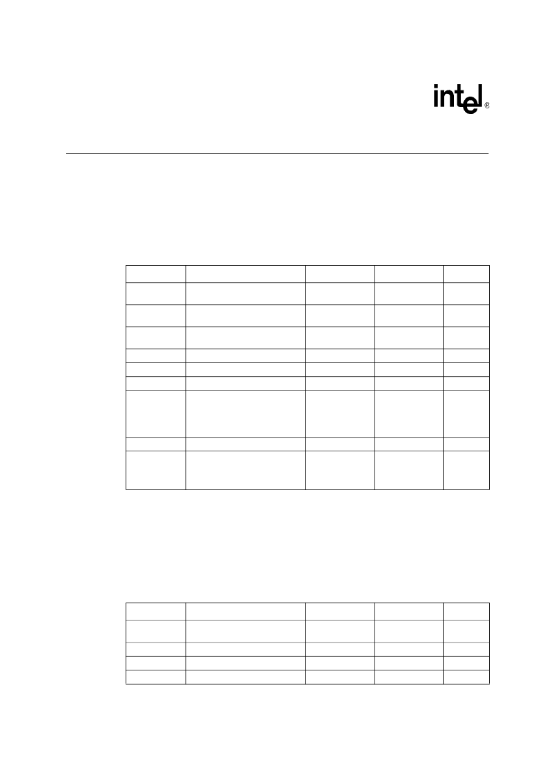
Table 1. Absolute Maximum Ratings
a
a. Maximum ratings are referenced to ground (VSS). Permanent device damage is likely to occur if the ratings in this table are
exceeded. These values should not be used as the limits for normal device operations.
b. The maximum value is the lesser value of 4.6 V or VDD(2.5) + 0.5 V. This specification applies to biasing the device to a steady
state for an indefinite duration. During normal device power-up, explicit power sequencing is not required.
c.
The maximum value is the lesser value of 4.6 V or VDD(2.5) + 0.5 V.
Symbol
Parameter
Min
Max
Unit
VDD (3.3)
DC supply voltage on VDDD or
AVDDH with respect to VSS
VSS - 0.5
4.6
V
VDD (2.5)
DC supply voltage on AVDDL with
respect to VSS
VSS - 0.5
4.6 or
VDD (2.5) + 0.5
b
V
VDD (1.5)
DC supply voltage on DVDD with
respect to VSS
VSS - 0.5
4.6 or
VDD (2.5) + 0.5
c
V
VDD
DC supply voltage
VSS - 0.5
4.6
V
VI / VO
LVTTL input voltage
VSS - 0.5
4.6
V
VI / VO
5 V compatible input voltage
VSS - 0.5
6.6
V
IO
DC output current (by cell type):
IOL = 3 mA
IOL = 6 mA
IOL - 12 mA
10
20
40
mA
TSTG
Storage temperature range
-40
125
C
ESD per MIL_STD-883 Test
Method 3015, Specification 2001V
Latchup Over/Undershoot: 150
mA, 125 C
VDD overstress:
VDD(3.3)(7.2 V)
V
Table 2. Recommended Operating Conditions
a
Symbol
Parameter
Min
Max
Unit
VDD (3.3)
DC supply voltage on VDDD or
AVDDH
3.0
3.6
V
VDD (2.5)
DC supply voltage on AVDDL
c
2.38
2.62
V
VDD (1.5)
DC supply voltage on DVDD
1.43
1.57
V
VIO
PCI bus voltage reference
3.0
5.25
V
相關(guān)PDF資料 |
PDF描述 |
|---|---|
| 8254 | PROGRAMMABLE INTERVAL TIMER |
| 82555 | 10/100 Mbps LAN physical layer interface |
| 82557 | Fast Ethernet PCI Bus Controller(快速以太網(wǎng) PCI總線控制器) |
| 82559 | Fast Ethernet Multifunction PCI/CARD bus controller(快速以太網(wǎng)多功能PCI/CARD 總線控制器) |
| 8255A-5 | PROGRAMMABLE PERIPHEAL INTERFACE |
相關(guān)代理商/技術(shù)參數(shù) |
參數(shù)描述 |
|---|---|
| 82546GB | 制造商:INT 功能描述: 制造商:undefined 功能描述: |
| 825470 | 功能描述:UC-EMLP (27X12 5) YE 制造商:phoenix contact 系列:* 零件狀態(tài):有效 標(biāo)準(zhǔn)包裝:10 |
| 82547-00000 | 制造商:3M Electronic Products Division 功能描述:ADAM ref. traded PUR |
| 825479-2 | 制造商:TE Connectivity 功能描述:MOD II VERT.MNT MAL - Bulk |
| 825479-3 | 制造商:TE Connectivity 功能描述:MOD II VERT.MNT MAL - Bulk |
發(fā)布緊急采購(gòu),3分鐘左右您將得到回復(fù)。