- 您現(xiàn)在的位置:買賣IC網(wǎng) > PDF目錄378216 > 82546EB (Intel Corp.) Dual Port Gigabit Ethernet Controller PDF資料下載
參數(shù)資料
| 型號: | 82546EB |
| 廠商: | Intel Corp. |
| 英文描述: | Dual Port Gigabit Ethernet Controller |
| 中文描述: | 雙端口千兆以太網(wǎng)控制器 |
| 文件頁數(shù): | 17/47頁 |
| 文件大?。?/td> | 281K |
| 代理商: | 82546EB |
第1頁第2頁第3頁第4頁第5頁第6頁第7頁第8頁第9頁第10頁第11頁第12頁第13頁第14頁第15頁第16頁當(dāng)前第17頁第18頁第19頁第20頁第21頁第22頁第23頁第24頁第25頁第26頁第27頁第28頁第29頁第30頁第31頁第32頁第33頁第34頁第35頁第36頁第37頁第38頁第39頁第40頁第41頁第42頁第43頁第44頁第45頁第46頁第47頁
Networking Silicon —
82546EB
Datasheet
11
3.2.5
Error Reporting Signals
3.2.6
Power Management Signals
3.2.7
Impedance Compensation Signals
3.2.8
SMB Signals
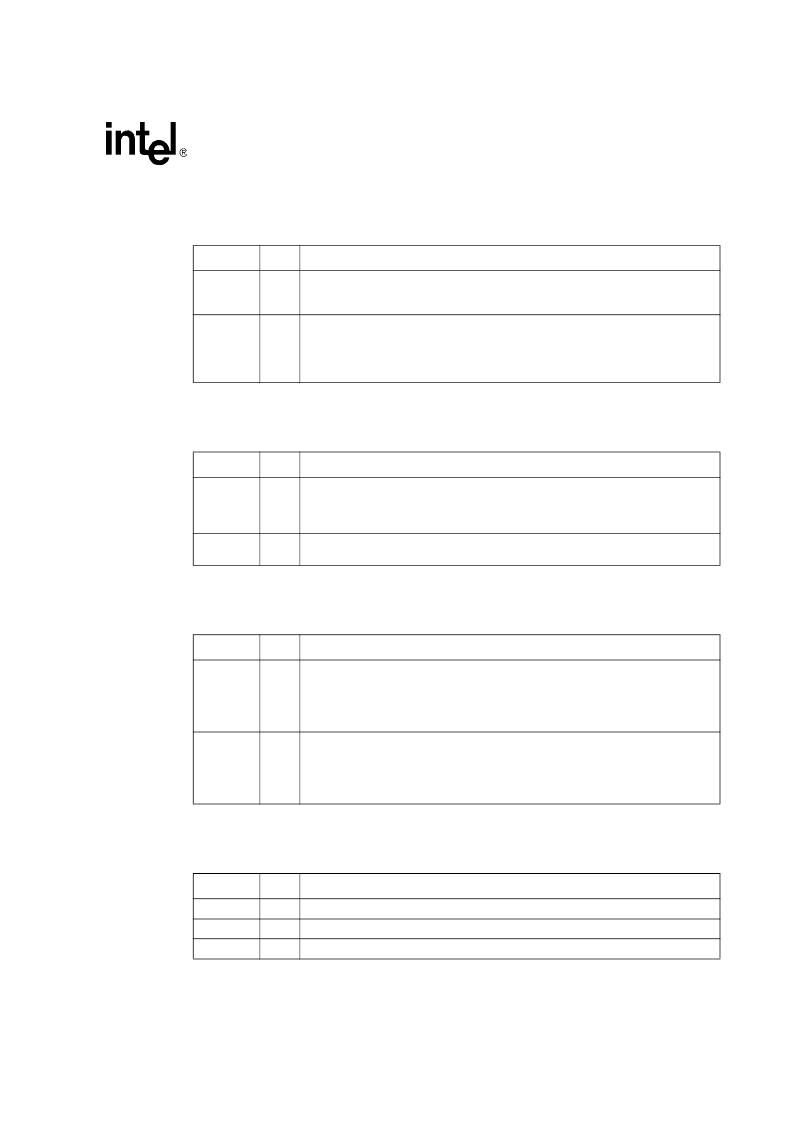
Symbol
Type
Name and Function
SERR#
OD
System Error.
The System Error signal is used by the
82546EB
controller to report
address parity errors. SERR# is open drain and is actively driven for a single PCI clock
when reporting the error.
PERR#
STS
Parity Error.
The Parity Error signal is used by the
82546EB
controller to report data
parity errors during all PCI transactions except by a Special Cycle. PERR# is sustained
tri-state and must be driven active by the
82546EB
controller two data clocks after a
data parity error is detected. The minimum duration of PERR# is one clock for each
data phase a data parity error is present.
Symbol
Type
Name and Function
PME#
OD
Power Management Event.
The
82546EB
device drives this signal low when it
receives a wake-up event and either the PME Enable bit in the Power Management
Control/Status Register or the Advanced Power Management Enable (APME) bit of the
Wake-up Control Register (WUC) is 1b.
AUX_PWR
I
Auxiliary Power.
If the Auxiliary Power signal is high, then auxiliary power is available
and the
82546EB
device should support the D3cold power state.
Symbol
Type
Name and Function
ZN_COMP
I/O
N Device Impedance Compensation.
This signal should be connected to an external
precision resistor (to VDD) that is indicative of the PCI
/PCI-X
trace load. This cell is
used to dynamically determine the drive strength required on the N-channel transistors
in the PCI
/PCI-X
I/O cells.
The internal pull-up impedance is nominally 20 K
with a minimum of 15 K
.
ZP_COMP
I/O
P Device Impedance Compensation.
This signal should be connected to an external
precision resistor (to VSS) that is indicative of the PCI
/PCI-X
trace load. This cell is
used to dynamically determine the drive strength required on the P-channel transistors
in the PCI
/PCI-X
I/O cells.
The internal pull-up impedance is nominally 20 K
with a minimum of 15 K
.
Symbol
Type
Name and Function
SMBCLK
I/O
SMB Clock.
The SMB Clock signal is an open drain signal for serial SMB interface.
SMBDATA
I/O
SMB Data.
The SMB Data signal is an open drain signal for serial SMB interface.
SMBALRT#
O
SMB Alert.
The SMB Alert signal is open drain for serial SMB interface.
相關(guān)PDF資料 |
PDF描述 |
|---|---|
| 8254 | PROGRAMMABLE INTERVAL TIMER |
| 82555 | 10/100 Mbps LAN physical layer interface |
| 82557 | Fast Ethernet PCI Bus Controller(快速以太網(wǎng) PCI總線控制器) |
| 82559 | Fast Ethernet Multifunction PCI/CARD bus controller(快速以太網(wǎng)多功能PCI/CARD 總線控制器) |
| 8255A-5 | PROGRAMMABLE PERIPHEAL INTERFACE |
相關(guān)代理商/技術(shù)參數(shù) |
參數(shù)描述 |
|---|---|
| 82546GB | 制造商:INT 功能描述: 制造商:undefined 功能描述: |
| 825470 | 功能描述:UC-EMLP (27X12 5) YE 制造商:phoenix contact 系列:* 零件狀態(tài):有效 標(biāo)準(zhǔn)包裝:10 |
| 82547-00000 | 制造商:3M Electronic Products Division 功能描述:ADAM ref. traded PUR |
| 825479-2 | 制造商:TE Connectivity 功能描述:MOD II VERT.MNT MAL - Bulk |
| 825479-3 | 制造商:TE Connectivity 功能描述:MOD II VERT.MNT MAL - Bulk |
發(fā)布緊急采購,3分鐘左右您將得到回復(fù)。