- 您現(xiàn)在的位置:買賣IC網(wǎng) > PDF目錄378216 > 82546EB (Intel Corp.) Dual Port Gigabit Ethernet Controller PDF資料下載
參數(shù)資料
| 型號(hào): | 82546EB |
| 廠商: | Intel Corp. |
| 英文描述: | Dual Port Gigabit Ethernet Controller |
| 中文描述: | 雙端口千兆以太網(wǎng)控制器 |
| 文件頁(yè)數(shù): | 21/47頁(yè) |
| 文件大小: | 281K |
| 代理商: | 82546EB |
第1頁(yè)第2頁(yè)第3頁(yè)第4頁(yè)第5頁(yè)第6頁(yè)第7頁(yè)第8頁(yè)第9頁(yè)第10頁(yè)第11頁(yè)第12頁(yè)第13頁(yè)第14頁(yè)第15頁(yè)第16頁(yè)第17頁(yè)第18頁(yè)第19頁(yè)第20頁(yè)當(dāng)前第21頁(yè)第22頁(yè)第23頁(yè)第24頁(yè)第25頁(yè)第26頁(yè)第27頁(yè)第28頁(yè)第29頁(yè)第30頁(yè)第31頁(yè)第32頁(yè)第33頁(yè)第34頁(yè)第35頁(yè)第36頁(yè)第37頁(yè)第38頁(yè)第39頁(yè)第40頁(yè)第41頁(yè)第42頁(yè)第43頁(yè)第44頁(yè)第45頁(yè)第46頁(yè)第47頁(yè)
Networking Silicon —
82546EB
Datasheet
15
3.7
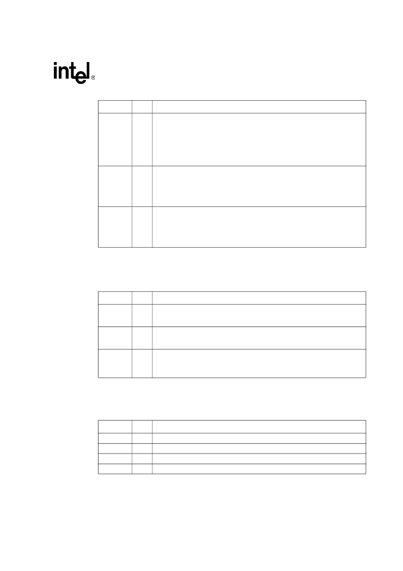
Serializer / Deserializer Signals
3.8
JTAG Test Interface Signals
MDIB[1]+/-
A
Media Dependent Interface B [1].
1000BASE-T
: In MDI configuration, MDIB[1]+/- corresponds to BI_DB+/-, and in MDI-X
configuration, MDIB[1]+/- corresponds to BI_DA+/-.
100BASE-TX
: In MDI configuration, MDIB[1]+/- is used for the receive pair, and in MDI-X
configuration, MDIB[1]+/- is used for the transit pair.
10BASE-T
: In MDI configuration, MDIB[1]+/- is used for the receive pair, and in MDI-X
configuration, MDIB[1]+/- is used for the transit pair.
MDIB[2]+/-
A
Media Dependent Interface B [2].
1000BASE-T
: In MDI configuration, MDIB[2]+/- corresponds to BI_DC+/-, and in MDI-X
configuration, MDIB[2]+/- corresponds to BI_DD+/-.
100BASE-TX
: Unused.
10BASE-T
: Unused.
MDIB[3]+/-
A
Media Dependent Interface B [3].
1000BASE-T
: In MDI configuration, MDIB[3]+/- corresponds to BI_DD+/-, and in MDI-X
configuration, MDIB[3]+/- corresponds to BI_DC+/-.
100BASE-TX
: Unused.
10BASE-T
: Unused.
Symbol
Type
Name and Function
RXA+/-
RXB +/-
I
SERDES Receive Pairs A and B.
These signals make the differential receive pair for
the 1.25 GHz serial interface. If the SERDES interface is not used, these pins should
not be connected.
TXA+/-
TXB +/-
O
SERDES Transmit Pairs A and B.
These signals make the differential transmit pair for
the 1.25 GHz serial interface. If the SERDES interface is not used, these pins should
not be connected.
SIG_
DETECT
(A and B)
I
Signal Detects A and B.
These pins indicate whether the SERDES signals
(connected to the 1.25 GHz serial interface) have been detected by the optical
transceivers. If the SERDES interface is not used, the SIG_DETECT inputs should be
connected to ground using pull-down resistors.
Symbol
Type
Name and Function
JTAG_TCK
I
JTAG Clock.
JTAG_TDI
I
JTAG TDI.
JTAG_TDO
O
JTAG TDO.
JTAG_TMS
I
JTAG TMS.
Symbol
Type
Name and Function
相關(guān)PDF資料 |
PDF描述 |
|---|---|
| 8254 | PROGRAMMABLE INTERVAL TIMER |
| 82555 | 10/100 Mbps LAN physical layer interface |
| 82557 | Fast Ethernet PCI Bus Controller(快速以太網(wǎng) PCI總線控制器) |
| 82559 | Fast Ethernet Multifunction PCI/CARD bus controller(快速以太網(wǎng)多功能PCI/CARD 總線控制器) |
| 8255A-5 | PROGRAMMABLE PERIPHEAL INTERFACE |
相關(guān)代理商/技術(shù)參數(shù) |
參數(shù)描述 |
|---|---|
| 82546GB | 制造商:INT 功能描述: 制造商:undefined 功能描述: |
| 825470 | 功能描述:UC-EMLP (27X12 5) YE 制造商:phoenix contact 系列:* 零件狀態(tài):有效 標(biāo)準(zhǔn)包裝:10 |
| 82547-00000 | 制造商:3M Electronic Products Division 功能描述:ADAM ref. traded PUR |
| 825479-2 | 制造商:TE Connectivity 功能描述:MOD II VERT.MNT MAL - Bulk |
| 825479-3 | 制造商:TE Connectivity 功能描述:MOD II VERT.MNT MAL - Bulk |
發(fā)布緊急采購(gòu),3分鐘左右您將得到回復(fù)。