- 您現(xiàn)在的位置:買賣IC網(wǎng) > PDF目錄67322 > 5962-0720601VXC 3-CH 14-BIT PROPRIETARY METHOD ADC, PARALLEL ACCESS, CQFP52 PDF資料下載
參數(shù)資料
| 型號: | 5962-0720601VXC |
| 元件分類: | ADC |
| 英文描述: | 3-CH 14-BIT PROPRIETARY METHOD ADC, PARALLEL ACCESS, CQFP52 |
| 封裝: | CERAMIC, QFP-52 |
| 文件頁數(shù): | 9/21頁 |
| 文件大小: | 433K |
| 代理商: | 5962-0720601VXC |
49.9
+
THS4304
ADS5424M
1:1
5 V
CM
RF
CM
VIN
From
50
Source
RG
CM
+
THS4304
5 V
CM
RF
RG
VREF
AIN
2.7 pF
14-Bit
105 MSPS
AIN
AIN VREF
ADS5424M
+5V
THS 4509
CM
348
348
100
100
69.8
VIN
From
50
Source
225
225
69.8
49.9
49.9
0.22
F
0.22
F
0.1
F
0.1
F
0.22
F
www.ti.com ....................................................................................................................................................................................................... SLWS194 – MAY 2008
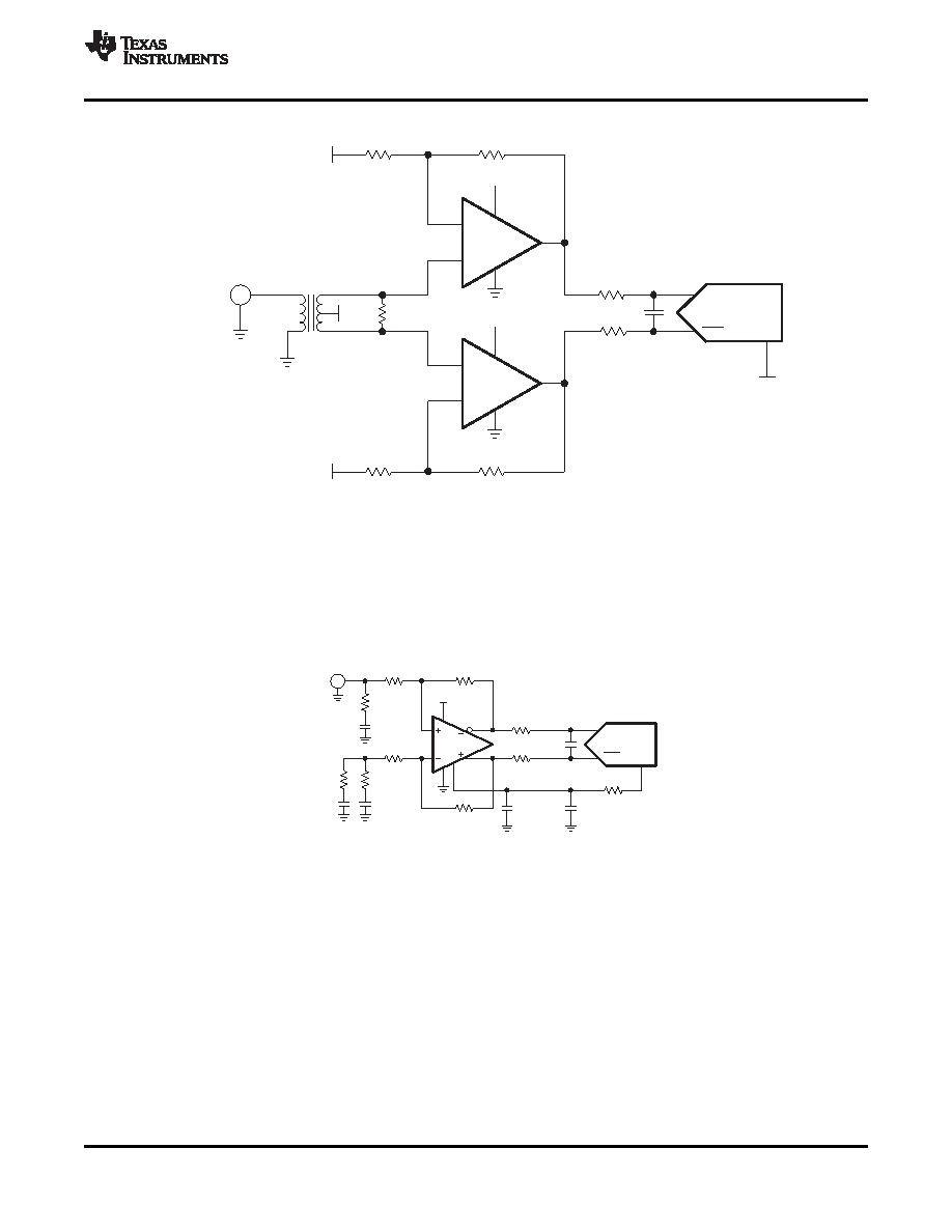
Figure 19. Using the THS4304 With the ADS5424
Texas Instruments offers a wide selection of single-ended operational amplifiers (including the THS3201,
THS3202 and OPA847) that can be selected depending on the application. An RF gain block amplifier, such as
Texas Instrument's THS9001, also can be used with an RF transformer for high input frequency applications. For
applications requiring dc-coupling with the signal source, instead of using a topology with three single-ended
amplifiers, a differential input/differential output amplifier like the THS4509 (see Figure 20) can be used, which
minimizes board space and reduces the number of components.
Figure 20. Using the THS4509 With the ADS5424
On this configuration, the THS4509 amplifier circuit provides 10 dB of gain, converts the single-ended input to
differential, and sets the proper input common-mode voltage to the ADS5424.
The 225
resistors and 2.7 pF capacitor between the THS4509 outputs and ADS5424 inputs (along with the
input capacitance of the ADC) limit the bandwidth of the signal to about 100 MHz (–3 dB).
For this test, an Agilent signal generator is used for the signal source. The generator is an ac-coupled 50
source. A bandpass filter is inserted in series with the input to reduce harmonics and noise from the signal
source.
Input termination is accomplished via the 69.8
resistor and 0.22
F capacitor to ground in conjunction with the
input impedance of the amplifier circuit. A 0.22
F capacitor and 49.9 resistor is inserted to ground across the
69.8
resistor and 0.22
F capacitor on the alternate input to balance the circuit.
Gain is a function of the source impedance, termination, and 348
feedback resistor. See the THS4509 data
sheet for further component values to set proper 50
termination for other common gains.
Copyright 2008, Texas Instruments Incorporated
17
Product Folder Link(s): ADS5424-SP
相關PDF資料 |
PDF描述 |
|---|---|
| 5962-0720601VXC | 3-CH 14-BIT PROPRIETARY METHOD ADC, PARALLEL ACCESS, CQFP52 |
| 5962-0720701VXC | 1-CH 13-BIT PROPRIETARY METHOD ADC, PARALLEL ACCESS, CQFP84 |
| 5962-0720801VXC | 1-CH 12-BIT PROPRIETARY METHOD ADC, PARALLEL ACCESS, CQFP84 |
| 5962-0724301HXC | 1-OUTPUT 66 W DC-DC REG PWR SUPPLY MODULE |
| 5962-0724305HXC | 1-OUTPUT 100 W DC-DC REG PWR SUPPLY MODULE |
相關代理商/技術參數(shù) |
參數(shù)描述 |
|---|---|
| 5962-0720701VXC | 制造商:TI 制造商全稱:Texas Instruments 功能描述:CLASS V, 13 BIT, 250 MSPS ANALOG-TO-DIGITAL CONVERTER |
| 5962-0720801VXC | 制造商:Texas Instruments 功能描述:ADS5463MHFG-V - Rail/Tube |
| 5962-0721201QXC | 制造商:INTERSIL 制造商全稱:Intersil Corporation 功能描述:Video Distribution Amplifier |
| 5962-0721301QHC | 制造商:INTERSIL 制造商全稱:Intersil Corporation 功能描述:500MHz Rail-to-Rail Amplifiers |
| 5962-0721301QXC | 制造商:INTERSIL 制造商全稱:Intersil Corporation 功能描述:500MHz Rail-to-Rail Amplifiers |
發(fā)布緊急采購,3分鐘左右您將得到回復。