- 您現在的位置:買賣IC網 > PDF目錄371440 > 29LV400C-90 (Macronix International Co., Ltd.) 4M-BIT [512K x 8 / 256K x 16] CMOS SINGLE VOLTAGE 3V ONLY FLASH MEMORY PDF資料下載
參數資料
| 型號: | 29LV400C-90 |
| 廠商: | Macronix International Co., Ltd. |
| 英文描述: | 4M-BIT [512K x 8 / 256K x 16] CMOS SINGLE VOLTAGE 3V ONLY FLASH MEMORY |
| 中文描述: | 4分位[為512k × 8 / 256K × 16] CMOS單電壓3V時僅閃存 |
| 文件頁數: | 13/68頁 |
| 文件大?。?/td> | 906K |
| 代理商: | 29LV400C-90 |
第1頁第2頁第3頁第4頁第5頁第6頁第7頁第8頁第9頁第10頁第11頁第12頁當前第13頁第14頁第15頁第16頁第17頁第18頁第19頁第20頁第21頁第22頁第23頁第24頁第25頁第26頁第27頁第28頁第29頁第30頁第31頁第32頁第33頁第34頁第35頁第36頁第37頁第38頁第39頁第40頁第41頁第42頁第43頁第44頁第45頁第46頁第47頁第48頁第49頁第50頁第51頁第52頁第53頁第54頁第55頁第56頁第57頁第58頁第59頁第60頁第61頁第62頁第63頁第64頁第65頁第66頁第67頁第68頁

13
P/N:PM1155
MX29LV400C T/B
REV. 1.5, APR. 24, 2006
erase margin has been achieved for the memory array
(no erase verification command is required). Sector
erase is a six-bus cycle operation. There are two "un-
lock" write cycles. These are followed by writing the set-
up command 80H. Two more "unlock" write cycles are
then followed by the sector erase command 30H. The
sector address is latched on the falling edge of WE# or
CE#, whichever happens later, while the command (data)
is latched on the rising edge of WE# or CE#, whichever
happens first. Sector addresses selected are loaded
into internal register on the sixth falling edge of WE# or
CE#, whichever happens later. Each successive sector
load cycle started by the falling edge of WE# or CE#,
whichever happens later must begin within 50us from
the rising edge of the preceding WE# or CE#, whichever
happens first. Otherwise, the loading period ends and
internal auto sector erase cycle starts. (Monitor Q3 to
determine if the sector erase timer window is still open,
see section Q3, Sector Erase Timer.) Any command other
than Sector Erase(30H) or Erase Suspend(B0H) during
the time-out period resets the device to read mode.
SECTOR ERASE COMMANDS
The Automatic Sector Erase does not require the de-
vice to be entirely pre-programmed prior to executing
the Automatic Sector Erase Set-up command and Au-
tomatic Sector Erase command. Upon executing the
Automatic Sector Erase command, the device will auto-
matically program and verify the sector(s) memory for
an all-zero data pattern. The system is not required to
provide any control or timing during these operations.
When the sector(s) is automatically verified to contain
an all-zero pattern, a self-timed sector erase and verify
begin. The erase and verify operations are complete
when either the data on Q7 is "1" at which time the de-
vice returns to the Read mode, or the data on Q6 stops
toggling for two consecutive read cycles at which time
the device returns to the Read mode. The system is not
required to provide any control or timing during these
operations.
When using the Automatic sector Erase algorithm, note
that the erase automatically terminates when adequate
Status
Q7
Q6
Q5
Q3
Q2
RY/
BY#
(Note1)
(Note2)
Byte Program in Auto Program Algorithm
Q7#
Toggle
0
N/A
No
0
Toggle
Auto Erase Algorithm
0
Toggle
0
1
Toggle
0
Erase Suspend Read
(Erase Suspended Sector)
1
No
0
N/A Toggle
1
Toggle
In Progress
Erase Suspended Mode
Erase Suspend Read
(Non-Erase Suspended Sector)
Data
Data
Data
Data
Data
1
Erase Suspend Program
Q7#
Toggle
0
N/A
N/A
0
Byte Program in Auto Program Algorithm
Q7#
Toggle
1
N/A
No
0
Toggle
Exceeded
Time Limits Auto Erase Algorithm
0
Toggle
1
1
Toggle
0
Erase Suspend Program
Q7#
Toggle
1
N/A
N/A
0
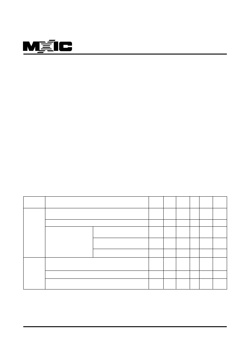
Table 7. Write Operation Status
Note:
1. Q7 and Q2 require a valid address when reading status information. Refer to the appropriate subsection for further details.
2. Q5 switches to '1' when an Auto Program or Auto Erase operation has exceeded the maximum timing limits.
See "Q5:Exceeded Timing Limits " for more information.
相關PDF資料 |
PDF描述 |
|---|---|
| 29LV650 | 64M (4M x 16) BIT |
| 29LV800BB-70 | 8M-BIT [1Mx8/512K x16] CMOS SINGLE VOLTAGE 3V ONLY FLASH MEMORY |
| 29LV800BB-90 | 8M-BIT [1Mx8/512K x16] CMOS SINGLE VOLTAGE 3V ONLY FLASH MEMORY |
| 29LV800BT-70 | 8M-BIT [1Mx8/512K x16] CMOS SINGLE VOLTAGE 3V ONLY FLASH MEMORY |
| 29LV800BT-90 | 8M-BIT [1Mx8/512K x16] CMOS SINGLE VOLTAGE 3V ONLY FLASH MEMORY |
相關代理商/技術參數 |
參數描述 |
|---|---|
| 29LV51215JU | 制造商: 功能描述: 制造商:undefined 功能描述: |
| 29LV512-15JU | 制造商: 功能描述: 制造商:undefined 功能描述: |
| 29LV640 | 制造商:MCNIX 制造商全稱:Macronix International 功能描述:flash memory |
| 29LV640DL90RZI | 制造商: 功能描述: 制造商:undefined 功能描述: |
| 29LV640MU90RPCI | 制造商: 功能描述: 制造商:undefined 功能描述: |
發(fā)布緊急采購,3分鐘左右您將得到回復。