- 您現(xiàn)在的位置:買賣IC網(wǎng) > PDF目錄24691 > 05F8025 IC-SM-QUAD 12 BIT DAC PDF資料下載
參數(shù)資料
| 型號(hào): | 05F8025 |
| 英文描述: | IC-SM-QUAD 12 BIT DAC |
| 中文描述: | 集成電路釤四路12位DAC |
| 文件頁數(shù): | 6/12頁 |
| 文件大小: | 502K |
| 代理商: | 05F8025 |

DAC8412/DAC8413
REV. C
–3–
(@ VDD = VLOGIC = +5.0 V
5%, VSS = 0.0 V, VREFH = +2.5 V, VREFL = 0.0 V, and
VSS = –5.0 V
5%, VREFL = –2.5 V, –40 C
≤ T
A
≤ +85 C unless otherwise noted.
See Note 1 for supply variations.)
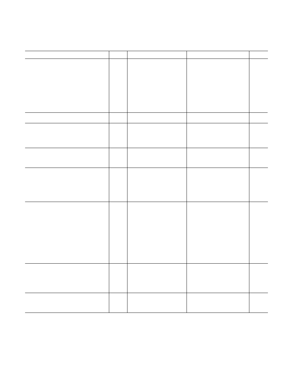
ELECTRICAL CHARACTERISTICS
Parameter
Symbol
Conditions
Min
Typ
Max
Units
Integral Linearity “E”
INL
1/2
±1
LSB
Integral Linearity “F”
INL
±2
LSB
Integral Linearity “E”
INL
VSS = 0.0 V; Note 2
±2
LSB
Integral Linearity “F”
INL
VSS = 0.0 V; Note 2
±4
LSB
Differential Linearity
DNL
Monotonic Over Temperature
–1
LSB
Min Scale Error
VZSE
VSS = –5.0 V
±4
LSB
Full-Scale Error
VFSE
VSS = –5.0 V
±4
LSB
Min Scale Error
VZSE
VSS = 0.0 V
±8
LSB
Full-Scale Error
VFSE
VSS = 0.0 V
±8
LSB
Min Scale Tempco
TCVZSE
100
ppm/
°C
Full-Scale Tempco
TCVFSE
100
ppm/
°C
MATCHING PERFORMANCE
Linearity Matching
±1
LSB
REFERENCE
Positive Reference Input Range
Note 3
VREFL + 2.5
VDD – 2 5
V
Negative Reference Input Range
VSS = 0.0 V
0
VREFH – 2.5 V
Negative Reference Input Range
VSS = –5.0 V
–2.5
VREFH – 2.5 V
Reference High Input Current
IREFH
Code 000H
–1.0
+1.0
mA
AMPLIFIER CHARACTERISTICS
Output Current
IOUT
–1.25
+1.25
mA
Settling Time
tS
to 0.01%
6
s
Slew Rate
SR
10% to 90%
2.2
V/
s
LOGIC CHARACTERISTICS
Logic Input High Voltage
VINH
TA = +25°C
2.4
V
Logic Input Low Voltage
VINL
TA = +25
°C
0.8
V
Logic Output High Voltage
VOH
IOH = +0.4 mA
2.4
V
Logic Output Low Voltage
VOL
IOL = –1.6 mA
0.45
V
Logic Input Current
IIN
1
A
Input Capacitance
CIN
8pF
LOGIC TIMING CHARACTERISTICS
Note 4
WRITE
Chip Select Write Pulse Width
tWCS
150
90
ns
Write Setup
tWS
tWCS = 150 ns
0
ns
Write Hold
tWH
tWCS = 150 ns
0
ns
Address Setup
tAS
0ns
Address Hold
tAH
0ns
Load Setup
tLS
70
30
ns
Load Hold
tLH
50
20
ns
Write Data Setup
tWDS
tWCS = 150 ns
20
ns
Write Data Hold
tWDH
tWCS = 150 ns
0
ns
Load Pulse Width
tLWD
180
130
ns
Reset Pulse Width
tRESET
150
110
ns
READ
Chip Select Read Pulse Width
tRCS
170
120
ns
Read Data Hold
tRDH
tRCS = 170 ns
20
ns
Read Data Setup
tRDS
tRCS = 170 ns
0
ns
Data to Hi Z
tDZ
CL = 10 pF
200
ns
Chip Select to Data
tCSD
CL = 100 pF
220
320
ns
SUPPLY CHARACTERISTICS
Power Supply Sensitivity
PSS
100
ppm/V
Positive Supply Current
IDD
712
mA
Negative Supply Current
ISS
VSS = –5.0 V
–10
mA
NOTES
1All supplies can be varied
±5%, and operation is guaranteed. Device is tested with V
DD = +4.75 V.
2For single supply operation only (V
REFL = 0.0 V, VSS = 0.0 V): Due to internal offset errors, INL and DNL are measured beginning at code 2 (002 H).
3Operation is guaranteed over this reference range, but linearity is neither tested nor guaranteed.
4All input control signals are specified with tr = tf = 5 ns (10% to 90% of +5 V) and timed from a voltage level of 1.6 V.
Specifications subject to change without notice.
相關(guān)PDF資料 |
PDF描述 |
|---|---|
| 05F8031 | IC-SM-QUAD 12 BIT DAC |
| 934051200112 | 40 MHz - 750 MHz RF/MICROWAVE WIDE BAND HIGH POWER AMPLIFIER |
| 934051230112 | 40 MHz - 750 MHz RF/MICROWAVE WIDE BAND HIGH POWER AMPLIFIER |
| 934051510185 | 100 mA, 50 V, PNP, Si, SMALL SIGNAL TRANSISTOR |
| 934031080215 | 100 mA, 50 V, PNP, Si, SMALL SIGNAL TRANSISTOR, TO-236AB |
相關(guān)代理商/技術(shù)參數(shù) |
參數(shù)描述 |
|---|---|
| 05FD101J03 | 制造商: 功能描述: 制造商:undefined 功能描述: |
| 05FD111J03 | 制造商: 功能描述: 制造商:undefined 功能描述: |
| 05FD161J03 | 制造商: 功能描述: 制造商:undefined 功能描述: |
| 05FD241J03 | 制造商: 功能描述: 制造商:undefined 功能描述: |
| 05FD271J03 | 制造商: 功能描述: 制造商:undefined 功能描述: |
發(fā)布緊急采購,3分鐘左右您將得到回復(fù)。