- 您現在的位置:買賣IC網 > PDF目錄379478 > UCC2941-ADJ (Electronic Theatre Controls, Inc.) 1V Synchronous Boost Converter PDF資料下載
參數資料
| 型號: | UCC2941-ADJ |
| 廠商: | Electronic Theatre Controls, Inc. |
| 英文描述: | 1V Synchronous Boost Converter |
| 中文描述: | 1V的同步升壓轉換器 |
| 文件頁數: | 7/8頁 |
| 文件大?。?/td> | 143K |
| 代理商: | UCC2941-ADJ |
7
UCC19411/2/3
UCC29411/2/3
UCC39411/2/3
ductor current ripple. At time t8, the 3.3V output is
satisfied and the converter can service the gate drive
voltage, VGD, which occurs at time t9
Shutdown Control
Shutdown of the UCC39411/2/3 is controlled via inter-
face with the SD/FB pin. Pulling the SD/FB pin low, for
all versions, causes the IC to go into shutdown. In the
UCC39412/3, the SD/FB pin is used solely as a shut-
down
function.
Therefore,
UCC39412 and UCC39413 can be directly controlled us-
ing conventional CMOS or TTL technology.
UCC39411, interface into the SD/FB is slightly more
complicated due to the added feedback function. When
feeding back the output voltage to the SD/FB pin on the
UCC39411, the IC requires a thevenin impedance of at
least 200k
(500k
for industrial/military applications) to
ground. Then, to accomplish shutdown of the IC, an
open drain device may be used.
the
SD/FB
pin
for
the
For the
Component Selection Inductor Selection
An inductor value of 22
μ
H will work well in most applica-
tions, but values between 10
μ
H to 100
μ
H are also ac-
ceptable. Lower value inductors typically offer lower ESR
and smaller physical size. Due to the nature of the
“bang-bang” controllers, larger inductor values will typi-
cally result in larger overall voltage ripple, because once
the output voltage level is satisfied the converter goes
discontinuous, resulting in the residual energy of the in-
ductor causing overshoot.
It is recommended to keep the ESR of the inductor below
0.15
for 200mW applications. A Coilcraft DT3316P-223
surface mount inductor is one choice since it has a cur-
rent rating of 1.5A and an ESR of 84m
.
Other choices for surface mount inductors are shown in
Table 1.
Output Capacitor Selection
Once the inductor value is selected the capacitor value
will determine the ripple of the converter. The worst case
peak to peak ripple of a cycle is determined by two com-
ponents, one is due to the charge storage characteristic,
and the other is the ESR of the capacitor. The worst
case ripple occurs when the inductor is operating at max
current and is expressed as follows:
(
)
)
C V
V
O
I
2
V
I
L
I
C
CL
CL
ESR
=
+
2
I
CL
= the peak inductor current = 550mA
V= Output ripple
V
O
= Output Voltage
V
I
= Input Voltage
C
ESR
= ESR of the output capacitor.
A Sanyo OS-CON series surface mount capacitor
(10SN100M) is one recommendation. This part has an
ESR rating of 90m
at 100
μ
F .
Other potential capacitor sources are shown in Table 2.
Input Capacitor Selection
Since the UCC39411 family does not require a large de-
coupling capacitor on the input voltage to operate prop-
erly, a 10
μ
F cap is sufficient for most applications.
Optimum efficiency will occur when the capacitor value is
large enough to decouple the source impedance, this
usually occurs for capacitor values in excess of 100
μ
F.
APPLICATION INFORMATION (continued)
MANUFACTURER
Sanyo Video
Components
San Diego, California
Tel: 619-661-6322
Fax: 619-661-1055
AVX
Sanford, Maine
Tel: 207-282-5111
Fax: 207-283-1941
Sprague
Concord, New Hampshire
Tel: 603-224-1961
PART NUMBER
OS-CON Series
TPS Series
695D Series
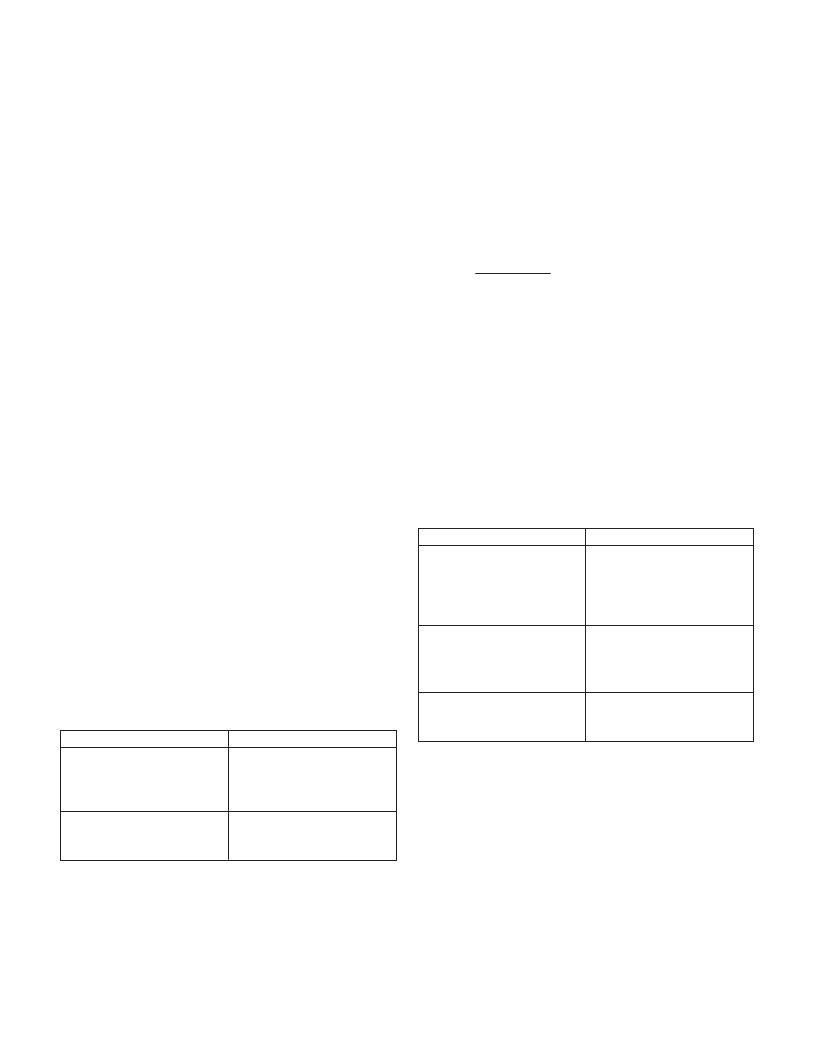
Table 2. Capacitor Suppliers
MANUFACTURER
Coilcraft
Cary, Illinois
Tel: 708-639-2361
Fax: 708-639-1469
Coiltronics
Boca Raton, Florida
Tel: 407-241-7876
PART NUMBERS
DT Series
CTX Series
Table 1. Inductor Suppliers
相關PDF資料 |
PDF描述 |
|---|---|
| UCC1946 | R8C Series, 20 Group, WDTO 48P6Q-A |
| UCC1972 | R8C Series, 20 Group, WDTO 48P6Q-A |
| UCC1973 | R8C Series, 20 Group, WDTO 48P6Q-A |
| UCC2752 | TOOLS,KITS,ELECTRONIC,NETWORK KIT, 22 PCS,COMPUTER ACCESSORIES,NETWORK MAINTENANCE KIT ,SPC TECHNOLOGY RoHS Compliant: NA |
| UCC28089DRB | PRIMARY-SIDE PUSH-PULL OSCILLATOR WITH DEAD-TIME CONTROL |
相關代理商/技術參數 |
參數描述 |
|---|---|
| UCC2941D-3 | 制造商:Rochester Electronics LLC 功能描述:- Bulk |
| UCC2941ND-3 WAF | 制造商:Texas Instruments 功能描述: |
| UCC2941ND-5 WAF | 制造商:Texas Instruments 功能描述: |
| UCC2941ND-ADJ WAF | 制造商:Texas Instruments 功能描述: |
| UCC29421N | 功能描述:DC/DC 開關控制器 High Freq Multimode Sync Controller RoHS:否 制造商:Texas Instruments 輸入電壓:6 V to 100 V 開關頻率: 輸出電壓:1.215 V to 80 V 輸出電流:3.5 A 輸出端數量:1 最大工作溫度:+ 125 C 安裝風格: 封裝 / 箱體:CPAK |
發(fā)布緊急采購,3分鐘左右您將得到回復。