- 您現(xiàn)在的位置:買賣IC網(wǎng) > PDF目錄379478 > UCC28089DRB (Texas Instruments, Inc.) PRIMARY-SIDE PUSH-PULL OSCILLATOR WITH DEAD-TIME CONTROL PDF資料下載
參數(shù)資料
| 型號: | UCC28089DRB |
| 廠商: | Texas Instruments, Inc. |
| 英文描述: | PRIMARY-SIDE PUSH-PULL OSCILLATOR WITH DEAD-TIME CONTROL |
| 中文描述: | 一次側(cè)推拉振蕩器死區(qū)時間控制 |
| 文件頁數(shù): | 7/19頁 |
| 文件大?。?/td> | 336K |
| 代理商: | UCC28089DRB |
SLUS623 SEPTEMBER 2004
7
www.ti.com
APPLICATION INFORMATION
The recommended oscillator frequency range is up to 1 MHz. In order to avoid noise issues, R
A
and R
B
should
be small enough for the oscillator to have at least 10
μ
A of current. There are two sets of oscillator programming
equations that model the oscillator over its wide programming range. Measure the charge and the discharge
times at the SYNC pin in order to avoid affecting the oscillator with probe impedances or output driver delays.
The approximate first order equations in the table are adequate for switching frequencies below 50 kHz and/or
discharge times that are greater than 1
μ
s. The specific requirements for using the first order equations versus
the second order equations are related to the timing capacitor size and the discharge resistor. Keep in mind that
the 1st order equations and 2nd order equations are merely approximations that are typically within +/20% of
the actual operating point. The frequency, charge and discharge times are relatively insensitive to temperature
but larger values of C
T
and R
B
exhibit the least sensitivity to temperature. Incidentally, the second order
equations apply for the operating conditions that are in the Electrical Characteristics table. The oscillator
frequency is set according to the following equations:
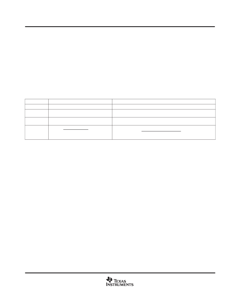
1ST ORDER EQUATIONS
RA > 300
AND CT > 300pF
2ND ORDER EQUATIONS
100
< RA < 300
OR 100pF < CT < 300pF
Condition
TCHARGE
0.169
RA
RBCT
0.175
RA
RB
CT
40
pF
20
ns
TDISCHARGE
1.36
RBCT
(1.37)
RB
44
CT
14
pF
20
ns
fOSC
5.9
8.0
RBCT
RA
1
TDISCHARGE
TCHARGE
Where R
A
and R
B
are in Ohms; C
T
is in Farads; f
OSC
is in Hz; t
CHARGE
and t
DISCHARGE
are in seconds.
The oscillator is optimized for a C
T
timing capacitor range from 100 pF to 1000 nF and R
B
more than 100
.
If the shortest discharge time possible is desired, it is permissible to short DIS to C
T
for all recommended C
T
values (100 pF to 0.100
μ
F).
SYNC:
This SYNC pin produces an output pulse from 0 to VDD that can be used to synchronize a secondary
side-buck controller to the free running isolating power stage. The proper timing of this signal enables zero
voltage switching on the primary side MOSFETs. The clean signal also solves a problem of getting a
synchronization signal from the secondary side of the transformer, which can have leakage inductance voltage
spikes that may cause false triggering. The SYNC pulse width is the oscillator discharge time, which is
approximately equal to the dead time. Pulse frequency is the oscillator frequency. During fault conditions, the
SYNC pulses are terminated and the SYNC output is held low for at least 56 oscillator cycles. During soft start,
SYNC precedes the first output pulse by at least one oscillator cycle.
CS:
Connect the current sense device to this pin. A voltage threshold of 0.725 V triggers a shutdown sequence.
An over-current fault triggers an immediate shutdown. After the fault clears, a total of 64 oscillator cycles are
required for an entire soft start sequence to occur. First, the outputs and SYNC are kept OFF for at least 56
oscillator cycles. Next, after one or two SYNC pulses, the soft start progressively increases the output duty ratio
over the next five to seven oscillator cycles.
相關(guān)PDF資料 |
PDF描述 |
|---|---|
| UCC2813-0QDRQ1 | LOW-POWER BICMOS CURRENT-MODE PWM |
| UCC2813PWTR-2 | Low Power Economy BiCMOS Current Mode PWM |
| UCC2813NTR-0 | Low Power Economy BiCMOS Current Mode PWM |
| UCC2813NTR-1 | Low Power Economy BiCMOS Current Mode PWM |
| UCC2813-2QDRQ1 | LOW-POWER BICMOS CURRENT-MODE PWM |
相關(guān)代理商/技術(shù)參數(shù) |
參數(shù)描述 |
|---|---|
| UCC28089DRBR | 制造商:Texas Instruments 功能描述:PRIMARY SIDE PUSH-PULL DRIVER WITH DEAD-TIME CONTROL - Tape and Reel |
| UCC28089DRBT | 制造商:Rochester Electronics LLC 功能描述:- Bulk |
| UCC28089DRG4 | 功能描述:功率驅(qū)動器IC Primary Side P-P Driver RoHS:否 制造商:Micrel 產(chǎn)品:MOSFET Gate Drivers 類型:Low Cost High or Low Side MOSFET Driver 上升時間: 下降時間: 電源電壓-最大:30 V 電源電壓-最小:2.75 V 電源電流: 最大功率耗散: 最大工作溫度:+ 85 C 安裝風(fēng)格:SMD/SMT 封裝 / 箱體:SOIC-8 封裝:Tube |
| UCC2808A-1 | 制造商:TI 制造商全稱:Texas Instruments 功能描述:LOW POWER CURRENT MODE PUSH-PULL PWM |
| UCC2808A-1EP | 制造商:TI 制造商全稱:Texas Instruments 功能描述:LOW POWER CURRENT MODE PUSH-PULL PWM |
發(fā)布緊急采購,3分鐘左右您將得到回復(fù)。