- 您現(xiàn)在的位置:買賣IC網(wǎng) > PDF目錄382720 > UCB1100 (NXP Semiconductors N.V.) Advanced modem/audio analog front-end PDF資料下載
參數(shù)資料
| 型號(hào): | UCB1100 |
| 廠商: | NXP Semiconductors N.V. |
| 英文描述: | Advanced modem/audio analog front-end |
| 中文描述: | 先進(jìn)的調(diào)制解調(diào)器/音頻模擬前端 |
| 文件頁數(shù): | 27/36頁 |
| 文件大小: | 290K |
| 代理商: | UCB1100 |
第1頁第2頁第3頁第4頁第5頁第6頁第7頁第8頁第9頁第10頁第11頁第12頁第13頁第14頁第15頁第16頁第17頁第18頁第19頁第20頁第21頁第22頁第23頁第24頁第25頁第26頁當(dāng)前第27頁第28頁第29頁第30頁第31頁第32頁第33頁第34頁第35頁第36頁

Philips Semiconductors
Preliminary specification
UCB1100
Advanced modem/audio analog front-end
1998 May 08
27
6.7.4
T
amb
= 0
°
C to 70
°
C, V
SSD
= V
SSA1
= V
SSA2
= V
SSA3
= 0V
V
DDD
= 3.3V
±
10%, V
DDA1
= 3.3V
±
10%, V
DDA2
= 3.3V
±
10%
AC Electrical Characteristics
SYMBOL
PARAMETER
NOTES
LIMITS
UNIT
MIN
TYP
MAX
1/t
sibclk
t
hsibclk
/t
sibclk
t
sclsy
t
hclsy
t
scldi
t
hcldi
t
pcldo
t
hcldo
t
pdido
t
pcdu
NOTES:
1. This is a requirement when an odd divisor is set either in the audio or in the telecom codec.
2. This is valid for all sib frame bits 0 to 63, except bits 17–20.
3. This is valid for the sib frame bits 17–20.
sibclk input frequency
0
15
MHz
duty cycle sibclk
Note 1
50
%
sibsync valid to falling edge sibclk
ns
sibsync hold after falling edge sibclk
ns
sibdin valid to falling edge sibclk
ns
sibdin hold after falling edge sibclk
ns
rising edge sibclk to valid sibdout
Note 2
20
ns
sibdout hold after rising sibclk edge
Note 3
ns
valid sibdin to valid sibdout
25
ns
6.8
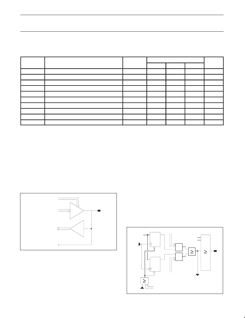
The UCB1100 has 10 programmable digital input/output (IO) pins.
These pins can be independently programmed as input or output
using the IO_mode[0:9] bits in the control register 1. The output data
is determined by the content of the io_data bits in the control register
0, while the actual status of these pins can be read from the
io_data[0:9] bits in the control register 0.
General Purpose IOs
The data on the io[0:9] pins are feed into the interrupt control block,
where they can generate an interrupt on the rising and/or falling
edge of these signals.
io_dat_in[x]
io_dat_out[x]
io_dir[x]
to interrupt module
io[x]
SN00157
Figure 32.
Block Diagram of I/O Pin Circuitry
6.9
The UCB1100 contains a programmable interrupt control block,
which can generate an interrupt for a ‘0’ to ‘1’ and/or a ‘1’ to ‘0’
transition on one or more of the IO[0:9] pins, the audio and telecom
clip detect, the adc_ready signal and the tspx_low and tsmx_low
signals.
Interrupt Generation
The interrupt generation mode is set by the int_ris_enabits in
register 2 and the int_fal_enabits in the control register 3. The
actual interrupt status of each signal can be read from the control
register 4. The interrupt status is clear whenever a ‘1’ to ‘0’ transition
is written in control register 4 for the corresponding bit. The irqout
pin presents the ‘OR’ function of all interrupt status bits and can be
used to give an interrupt to the system controller.
The interrupt controller is implemented asynchronously. This provide
the possibly to generate interrupts when the sibclk is stopped,
e.g., an interrupt can be generated in power down mode, when the
touch screen is pressed or when the state of one of the io pins
changes.
D
R
irqout
int_stat[x]
register 4 (read)
fal_int_ena[x]
&
&
D
R
ris_int_ena[x]
‘1’
int_clear[x]
reset
int.
source
‘OR’ tree
SN00158
Figure 33.
Block Diagram of the Interrupt Controller
相關(guān)PDF資料 |
PDF描述 |
|---|---|
| UCB1100LP | Advanced modem/audio analog front-end |
| UCB1200 | Advanced modem/audio analog front-end |
| UCB1200BE | Advanced modem/audio analog front-end |
| UCB1300 | Advanced modem/audio analog front-end |
| UCB1300BE | Advanced modem/audio analog front-end |
相關(guān)代理商/技術(shù)參數(shù) |
參數(shù)描述 |
|---|---|
| UCB1100LP | 制造商:PHILIPS 制造商全稱:NXP Semiconductors 功能描述:Advanced modem/audio analog front-end |
| UCB1100LP/X3 | 制造商:PHILIPS 制造商全稱:NXP Semiconductors 功能描述:Advanced modem/audio analog front-end |
| UCB-12 | 功能描述:斷路器 CIRCUIT BREAKER RoHS:否 制造商:Phoenix Contact 產(chǎn)品:Device Circuit Breakers 產(chǎn)品類型:Thermomagnetic 電流額定值:2 A 電壓額定值 AC:240 V, 277 V 電壓額定值 DC:50 V 極數(shù):1 Pole 執(zhí)行器類型:Slide 電路功能:Trip Free 系列:CB TM1 工作溫度范圍:- 30 C to + 60 C 照明:No |
| UCB1200 | 制造商:PHILIPS 制造商全稱:NXP Semiconductors 功能描述:Advanced modem/audio analog front-end |
| UCB1200B | 制造商:未知廠家 制造商全稱:未知廠家 功能描述:UCB1200B |
發(fā)布緊急采購,3分鐘左右您將得到回復(fù)。