- 您現(xiàn)在的位置:買賣IC網(wǎng) > PDF目錄385931 > TLK2201AIRCPR (Texas Instruments, Inc.) ETHERNET TRANSCEIVERS PDF資料下載
參數(shù)資料
| 型號: | TLK2201AIRCPR |
| 廠商: | Texas Instruments, Inc. |
| 英文描述: | ETHERNET TRANSCEIVERS |
| 中文描述: | 以太網(wǎng)收發(fā)器 |
| 文件頁數(shù): | 9/21頁 |
| 文件大小: | 343K |
| 代理商: | TLK2201AIRCPR |
TLK2201A, TLK2201AI
ETHERNET TRANSCEIVERS
SLLS572
–
JUNE 2003
9
POST OFFICE BOX 655303
DALLAS, TEXAS 75265
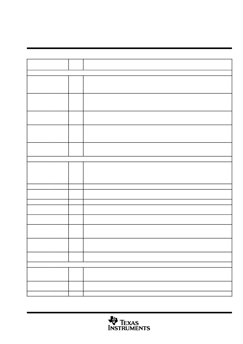
Terminal Functions (Continued)
TERMINAL
I/O
DESCRIPTION
NAME
NO.
SIGNAL (Continued)
RBCMODE
32
I
P/D
Receive clock mode select. When RBCMODE and MODESEL are low, half-rate clocks are output on
RBC0 and RBC1. When MODESEL is low and RBCMODE is high, a full baud-rate clock is output on
RBC0 and RBC1 is held low. When MODESEL is high, RBCMODE is ignored and a full baud-rate clock is
output on RBC0 and RBC1 is held low.
SYNCEN
24
I
P/U
Synchronous function enable. When SYNCEN is high, the internal synchronization function is activated.
When this function is activated, the transceiver detects the K28.5 comma character (0011111 negative
beginning disparity) in the serial data stream and realigns data on byte boundaries if required. When
SYNCEN is low, serial input data is unframed in RD0
–
RD9.
SYNC/PASS
47
O
Synchronous detect. The SYNC output is asserted high upon detection of the comma pattern in the serial
data path. SYNC pulses are output only when SYNCEN is activated (asserted high). In PRBS test mode
(PRBSEN=high), SYNC/PASS outputs the status of the PRBS test results (high=pass).
LOS
26
O
Loss of signal. Indicates a loss of signal on the high-speed differential inputs RXP and RXN.
If magnitude of RXP
–
RXN > 150 mV, LOS = 1, valid input signal
If magnitude of RXP
–
RXN < 150 mV and > 50 mV, LOS is undefined
If magnitude of RXP
–
RXN < 50 mV, LOS = 0, loss of signal
MODESEL
15
I
P/D
Mode select. This terminal selects between the 10-bit interface and a reduced 5-bit DDR interface. When
low the 10-bit interface (TBI) is selected. When pulled high, the 5-bit DDR mode is selected. The default
mode is the TBI.
TEST
LOOPEN
19
I
P/D
Loop enable. When LOOPEN is high (active), the internal loop-back path is activated. The transmitted
serial data is directly routed to the inputs of the receiver. This provides a self-test capability in conjunction
with the protocol device. The TXP and TXN outputs are held in a high-impedance state during the
loop-back test. LOOPEN is held low during standard operational state with external serial outputs and
inputs active.
TCK
49
I
Test clock. IEEE1149.1 (JTAG)
JTDI
48
I
P/U
Test data input. IEEE1149.1 (JTAG)
JTDO
27
O
Test data output. IEEE1149.1 (JTAG)
JTRSTN
56
I
P/U
Reset signal. IEEE1149.1 (JTAG)
JTMS
55
I
P/U
Test mode select. IEEE1149.1 (JTAG)
ENABLE
28
I
P/U
When this terminal is low, the device is disabled for Iddq testing. RD0
–
RD9, RBCn, TXP, and TXN are
high impedance. The pullup and pulldown resistors on any input are disabled. When ENABLE is high, the
device operates normally.
PRBSEN
16
I
P/D
PRBS enable. When PRBSEN is high, the PRBS generation circuitry is enabled. The PRBS verification
circuit in the receive side is also enabled. A PRBS signal can be fed to the receive inputs and checked for
errors, that are reported by the SYNC/PASS terminal indicating low.
TESTEN
17
I
P/D
Manufacturing test terminal
POWER
VDD
5, 10, 20,
23, 29, 37,
42, 50, 63
Supply
Digital logic power. Provides power for all digital circuitry and digital I/O buffers.
VDDA
53, 57, 59,
60
Supply
Analog power. VDDA provides power for the high-speed analog circuits, receiver, and transmitter
VDDPLL
P/D = Internal pulldown
P/U = Internal pullup
18
Supply
PLL power. Provides power for the PLL circuitry. This terminal requires additional filtering.
相關(guān)PDF資料 |
PDF描述 |
|---|---|
| TLN103A | INFRARED LED FOR PHOTOSENSORS |
| TLN115A | LED GAAS |
| TLOE156P | InGaAlP Orange Light Emission(InGaAlP橙色發(fā)光燈(LED照明燈)) |
| TLOH156P | Panel Circuit Indicator(平板電路指示器(橙色LED)) |
| TLOH157P | Panel Circuit Indicator(平板電路指示器(橙色LED)) |
相關(guān)代理商/技術(shù)參數(shù) |
參數(shù)描述 |
|---|---|
| TLK2201AIRCPRG4 | 功能描述:以太網(wǎng) IC 1.0 to 1.6 Gbps Gb Ethernet Transceiver RoHS:否 制造商:Micrel 產(chǎn)品:Ethernet Switches 收發(fā)器數(shù)量:2 數(shù)據(jù)速率:10 Mb/s, 100 Mb/s 電源電壓-最大:1.25 V, 3.45 V 電源電壓-最小:1.15 V, 3.15 V 最大工作溫度:+ 85 C 封裝 / 箱體:QFN-64 封裝:Tray |
| TLK2201AJR | 制造商:TI 制造商全稱:Texas Instruments 功能描述:1.0Gb to 1.6Gb SMALL FORM-FACTOR ETHERNET TRANSCEIVER |
| TLK2201AJRGQE | 功能描述:以太網(wǎng) IC 1.0 to 1.6 Gbps Ethernet Trnscvr RoHS:否 制造商:Micrel 產(chǎn)品:Ethernet Switches 收發(fā)器數(shù)量:2 數(shù)據(jù)速率:10 Mb/s, 100 Mb/s 電源電壓-最大:1.25 V, 3.45 V 電源電壓-最小:1.15 V, 3.15 V 最大工作溫度:+ 85 C 封裝 / 箱體:QFN-64 封裝:Tray |
| TLK2201AJRZQE | 功能描述:以太網(wǎng) IC 1.0-1.6 Gbps Gigabit Ethernet Trncvr RoHS:否 制造商:Micrel 產(chǎn)品:Ethernet Switches 收發(fā)器數(shù)量:2 數(shù)據(jù)速率:10 Mb/s, 100 Mb/s 電源電壓-最大:1.25 V, 3.45 V 電源電壓-最小:1.15 V, 3.15 V 最大工作溫度:+ 85 C 封裝 / 箱體:QFN-64 封裝:Tray |
| TLK2201ARCP | 功能描述:以太網(wǎng) IC 1.0 to 1.6 Gbps Gb Ethernet Transceiver RoHS:否 制造商:Micrel 產(chǎn)品:Ethernet Switches 收發(fā)器數(shù)量:2 數(shù)據(jù)速率:10 Mb/s, 100 Mb/s 電源電壓-最大:1.25 V, 3.45 V 電源電壓-最小:1.15 V, 3.15 V 最大工作溫度:+ 85 C 封裝 / 箱體:QFN-64 封裝:Tray |
發(fā)布緊急采購,3分鐘左右您將得到回復(fù)。