- 您現(xiàn)在的位置:買賣IC網(wǎng) > PDF目錄373629 > TEA2028 (意法半導(dǎo)體) APPLICATION NOTE PDF資料下載
參數(shù)資料
| 型號: | TEA2028 |
| 廠商: | 意法半導(dǎo)體 |
| 英文描述: | APPLICATION NOTE |
| 中文描述: | 應(yīng)用筆記 |
| 文件頁數(shù): | 6/47頁 |
| 文件大小: | 532K |
| 代理商: | TEA2028 |
第1頁第2頁第3頁第4頁第5頁當(dāng)前第6頁第7頁第8頁第9頁第10頁第11頁第12頁第13頁第14頁第15頁第16頁第17頁第18頁第19頁第20頁第21頁第22頁第23頁第24頁第25頁第26頁第27頁第28頁第29頁第30頁第31頁第32頁第33頁第34頁第35頁第36頁第37頁第38頁第39頁第40頁第41頁第42頁第43頁第44頁第45頁第46頁第47頁
V - FUNCTIONAL DESCRIPTION
Majority of the on-chipanalogfunctionswere com-
puter simulated and results such as temperature
variation, technological characteristic dispersion
and stability, have led to the enhancement and
implementationof actuallyemployed structures.A
parallel in-depth study of the device implemented
in form of integrated sub-sections is provided to
analyze the overallperformancein a TVset.
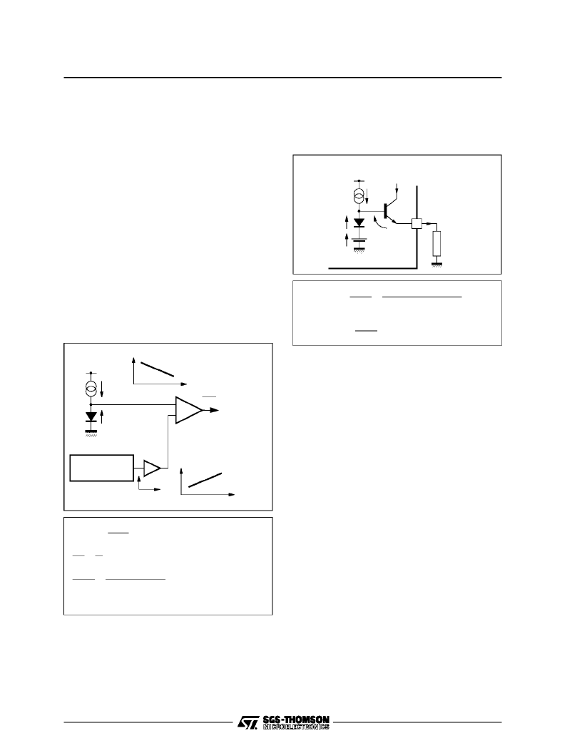
V.1 - Internal Voltage and Current References
V.1.1 - 1.26V Voltagereference
For optimum operation of the device, an accurate
and temperature-stable voltage generator inde-
pendent from V
CC
variations is used (Band-gap
typegenerator).
The generated1.26V is particularlyused asrefer-
ence setting on input comparators.
V.1.1.1 - Generatorblock diagram
V
BE
I
T
V
BE
λ
A
λ
GENERATOR
-2mV/
°
C
T
+0.086mV/
°
C
dt
dV
O
= 0
V
O
V
BE
=
= 1.26V
+ A.
λ
Σ
2
Figure3
with
λ
=K
T
dT=K
dV
BE
dT
if A
λ
= 1.26 - V
BE
Then : V
O
= 1.26V (temperature-independant)
q
= 25.7mV at + 25
o
C
q= + 0.086mV/
o
C
=V
BE
(
25’
)
1.26
T
= - 2mV/
o
C
In practice,maximum drift dueto temperaturecan
be + 0.23mV/
o
C
i.e.,
±
1.5% for a
T of 80
o
C.
14
V
V
BE1
BE2
1.26V
Band
Gap
I
REF
I
14
R
EXT
3.32k
1%
V
CC
+
2
Figure 4
V.1.2 - Current reference
This is implemented using the 1.26V generator in
combinationwith an externalresistor.
I
REF
≈
I
14
=V
14
R
EXT
=1.26
+
V
BE1
V
BE2
Let’s I
14
= I andV
EB1
= V
BE2
then : I
REF
=1.26
R
EXT
= 380
μ
A
R
EXY
Thus, it follows that I
REF
is accurate and inde-
pendent of both V
CC
and temperature.
A set of current generators proportional to I
REF
current are used in variouscircuit blocks.
V.2 - Line Sync. Extraction
Horizontal and vertical time bases should be syn-
chronized with corresponding sync. pulses trans-
mittedinside theinfra-black portion ofvideo signal.
The duty of this stage is to extract these sync
pulses. The output signal, called composite sync,
contains the vertical sync which is transmitted by
simple inversion of line sync. pulses.
The vertical sync pulse is then extracted from this
compositesignal.
The main advantage of this arrangement is its
ability to operate at video input signal levels falling
within 0.2V to 3V peak-to-peak range and at any
average value.
The operating principle is to lock the black levelof
the inputsignal (Pin27)ontointernalyfixedvoltage
(V
N
) andthenmemorizetheaverage voltageofthe
sync pulse by using an integrating capacitor con-
nected to Pin 26.
Finally, the composite sync signal isdelivered by a
comparator the inputs of whichare driven by V
50%
and video signals.
TEA2028 - TEA2029APPLICATIONNOTE
6/46
相關(guān)PDF資料 |
PDF描述 |
|---|---|
| TEA2028B | SWITCH MODE POWER SUPPLY PRIMARY CIRCUIT |
| TEA2128 | SWITCH MODE POWER SUPPLY PRIMARY CIRCUIT |
| TEA2164S | SWITCH MODE POWER SUPPLY PRIMARY CIRCUIT |
| TEA2029C | COLOR TV SCANNING AND POWER SUPPLY PROCESSOR |
| TEA2031A | COLOR TV EAST-WEST CORRECTION |
相關(guān)代理商/技術(shù)參數(shù) |
參數(shù)描述 |
|---|---|
| TEA2028B | 制造商:STMICROELECTRONICS 制造商全稱:STMicroelectronics 功能描述:COLOR TV SCANNING AND POWER SUPPLY PROCESSOR |
| TEA2028-TEA2029 | 制造商:STMICROELECTRONICS 制造商全稱:STMicroelectronics 功能描述:APPLICATION NOTE |
| TEA2029 | 制造商:STMICROELECTRONICS 制造商全稱:STMicroelectronics 功能描述:APPLICATION NOTE |
| TEA2029C | 制造商:STMICROELECTRONICS 制造商全稱:STMicroelectronics 功能描述:COLOR TV SCANNING AND POWER SUPPLY PROCESSOR |
| TEA2029CV | 制造商:TEMIC 制造商全稱:TEMIC Semiconductors 功能描述:Timing Processor (LINE, FRAME, SMPS) for TV Sets |
發(fā)布緊急采購,3分鐘左右您將得到回復(fù)。