- 您現(xiàn)在的位置:買賣IC網(wǎng) > PDF目錄98145 > ST72T774S9T1 (STMICROELECTRONICS) 8-BIT, OTPROM, 8 MHz, MICROCONTROLLER, PQFP44 PDF資料下載
參數(shù)資料
| 型號(hào): | ST72T774S9T1 |
| 廠商: | STMICROELECTRONICS |
| 元件分類: | 微控制器/微處理器 |
| 英文描述: | 8-BIT, OTPROM, 8 MHz, MICROCONTROLLER, PQFP44 |
| 封裝: | TQFP-44 |
| 文件頁(yè)數(shù): | 20/144頁(yè) |
| 文件大?。?/td> | 1280K |
| 代理商: | ST72T774S9T1 |
第1頁(yè)第2頁(yè)第3頁(yè)第4頁(yè)第5頁(yè)第6頁(yè)第7頁(yè)第8頁(yè)第9頁(yè)第10頁(yè)第11頁(yè)第12頁(yè)第13頁(yè)第14頁(yè)第15頁(yè)第16頁(yè)第17頁(yè)第18頁(yè)第19頁(yè)當(dāng)前第20頁(yè)第21頁(yè)第22頁(yè)第23頁(yè)第24頁(yè)第25頁(yè)第26頁(yè)第27頁(yè)第28頁(yè)第29頁(yè)第30頁(yè)第31頁(yè)第32頁(yè)第33頁(yè)第34頁(yè)第35頁(yè)第36頁(yè)第37頁(yè)第38頁(yè)第39頁(yè)第40頁(yè)第41頁(yè)第42頁(yè)第43頁(yè)第44頁(yè)第45頁(yè)第46頁(yè)第47頁(yè)第48頁(yè)第49頁(yè)第50頁(yè)第51頁(yè)第52頁(yè)第53頁(yè)第54頁(yè)第55頁(yè)第56頁(yè)第57頁(yè)第58頁(yè)第59頁(yè)第60頁(yè)第61頁(yè)第62頁(yè)第63頁(yè)第64頁(yè)第65頁(yè)第66頁(yè)第67頁(yè)第68頁(yè)第69頁(yè)第70頁(yè)第71頁(yè)第72頁(yè)第73頁(yè)第74頁(yè)第75頁(yè)第76頁(yè)第77頁(yè)第78頁(yè)第79頁(yè)第80頁(yè)第81頁(yè)第82頁(yè)第83頁(yè)第84頁(yè)第85頁(yè)第86頁(yè)第87頁(yè)第88頁(yè)第89頁(yè)第90頁(yè)第91頁(yè)第92頁(yè)第93頁(yè)第94頁(yè)第95頁(yè)第96頁(yè)第97頁(yè)第98頁(yè)第99頁(yè)第100頁(yè)第101頁(yè)第102頁(yè)第103頁(yè)第104頁(yè)第105頁(yè)第106頁(yè)第107頁(yè)第108頁(yè)第109頁(yè)第110頁(yè)第111頁(yè)第112頁(yè)第113頁(yè)第114頁(yè)第115頁(yè)第116頁(yè)第117頁(yè)第118頁(yè)第119頁(yè)第120頁(yè)第121頁(yè)第122頁(yè)第123頁(yè)第124頁(yè)第125頁(yè)第126頁(yè)第127頁(yè)第128頁(yè)第129頁(yè)第130頁(yè)第131頁(yè)第132頁(yè)第133頁(yè)第134頁(yè)第135頁(yè)第136頁(yè)第137頁(yè)第138頁(yè)第139頁(yè)第140頁(yè)第141頁(yè)第142頁(yè)第143頁(yè)第144頁(yè)

ST72774/ST727754/ST72734
116/144
4.9 PWM/BRM GENERATOR (DAC)
4.9.1 Introduction
This PWM/BRM peripheral includes two types of
PWM/BRM outputs, with differing step resolutions
based on the Pulse Width Modulator (PWM) and
Binary Rate Multiplier (BRM) Generator technique
are available. It allows the digital to analog
conversion
(DAC)
when
used
with
external
filtering.
4.9.2 Main Features
s
Fixed frequency: fCPU/64
s
Resolution: T
CPU
s
10-Bit PWM/BRM generator with a step of
V
DD/2
10 (5mV if V
DD=5V)
4.9.3 Functional Description
4.9.3.1 PWM/BRM
The 10 bits of the 10-bit PWM/BRM are distributed
as 6 PWM bits and 4 BRM bits. The generator
consists of a 12-bit counter (common for all
channels), a comparator and the PWM/BRM
generation logic.
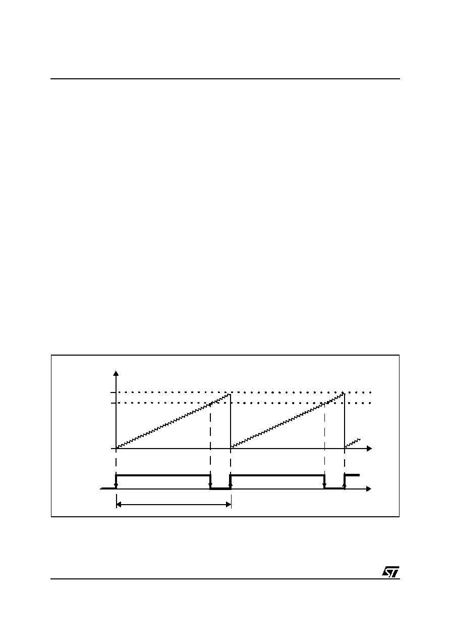
PWM Generation
The counter increments continuously, clocked at
internal
CPU
clock.
Whenever
the
6
least
significant bits of the counter (defined as the PWM
counter) overflow, the output level for all active
channels is set.
The state of the PWM counter is continuously
compared to the PWM binary weight for each
channel, as defined in the relevant PWM register,
and when a match occurs the output level for that
channel is reset.
This Pulse Width modulated signal must be
filtered, using an external RC network placed as
close as possible to the associated pin. This
provides an analog voltage proportional to the
average charge passed to the external capacitor.
Thus for a higher mark/space ratio (High time
much greater than Low time) the average output
voltage is higher. The external components of the
RC network should be selected for the filtering
level required for control of the system variable.
Each output may individually have its polarity
inverted by software, and can also be used as a
logical output.
Figure 69. PWM Generation
COUNTER
63
COMPARE
VALUE
OVERFLOW
000
t
PWM OUTPUT
t
T
CPU x 64
相關(guān)PDF資料 |
PDF描述 |
|---|---|
| ST7294C6B6 | 8-BIT, MROM, 4 MHz, MICROCONTROLLER, PDIP28 |
| ST72T94C6M6 | 8-BIT, OTPROM, MICROCONTROLLER, PDSO28 |
| ST72C171K2B6 | 8-BIT, FLASH, 8 MHz, MICROCONTROLLER, PDIP32 |
| ST72E85A5G0 | 8-BIT, UVPROM, 4.332 MHz, MICROCONTROLLER, CQFP80 |
| ST72F321J9T7 | 8-BIT, FLASH, 8 MHz, MICROCONTROLLER, PQFP44 |
相關(guān)代理商/技術(shù)參數(shù) |
參數(shù)描述 |
|---|---|
| ST730 | 制造商:IRF 制造商全稱:International Rectifier 功能描述:PHASE CONTROL THYRISTORS Hockey Puk Version |
| ST7-30 | 制造商:SUPERWORLD 制造商全稱:Superworld Electronics 功能描述:POWER TRANSFORMER |
| ST-7300 | 制造商:GC Electronics 功能描述: |
| ST730186-3 | 制造商:KEMET Corporation 功能描述: 制造商:KET 功能描述: |
| ST730268-1 | 制造商:KEMET Corporation 功能描述: 制造商:KET 功能描述: |
發(fā)布緊急采購(gòu),3分鐘左右您將得到回復(fù)。