- 您現(xiàn)在的位置:買賣IC網(wǎng) > PDF目錄369945 > PA28F008SA-120 (INTEL CORP) 8-MBIT (1-MBIT x 8) FlashFileTM MEMORY PDF資料下載
參數(shù)資料
| 型號(hào): | PA28F008SA-120 |
| 廠商: | INTEL CORP |
| 元件分類: | PROM |
| 英文描述: | 8-MBIT (1-MBIT x 8) FlashFileTM MEMORY |
| 中文描述: | 1M X 8 FLASH 12V PROM, 120 ns, PDSO44 |
| 封裝: | 0.525 X 1.110 INCH, PLASTIC, SOP-44 |
| 文件頁數(shù): | 19/33頁 |
| 文件大小: | 466K |
| 代理商: | PA28F008SA-120 |
第1頁第2頁第3頁第4頁第5頁第6頁第7頁第8頁第9頁第10頁第11頁第12頁第13頁第14頁第15頁第16頁第17頁第18頁當(dāng)前第19頁第20頁第21頁第22頁第23頁第24頁第25頁第26頁第27頁第28頁第29頁第30頁第31頁第32頁第33頁

28F008SA
ABSOLUTE MAXIMUM RATINGS
*
Operating Temperature
During Read àààààààààààààààààà0
§
C to
a
70
§
C
(1)
During Block Erase/Byte Write àààà0
§
C to
a
70
§
C
Temperature Under Biasààààààààà
b
10
§
C to
a
80
§
C
Storage Temperature àààààààààà
b
65
§
C to
a
125
§
C
Voltage on Any Pin
(except V
CC
and V
PP
)
with Respect to GND àààààààà
b
2.0V to
a
7.0V
(2)
V
PP
Program Voltage with
Respect to GND during
Block Erase/Byte Write ààà
b
2.0V to
a
14.0V
(2, 3)
V
CC
Supply Voltage
with Respect to GND àààààààà
b
2.0V to
a
7.0V
(2)
Output Short Circuit Currentààààààààààààà100 mA
(4)
NOTICE: This data sheet contains preliminary infor-
mation on new products in production. The specifica-
tions are subject to change without notice. Verify with
your local Intel Sales office that you have the latest
data sheet before finalizing a design.
*
WARNING: Stressing the device beyond the ‘‘Absolute
Maximum Ratings’’ may cause permanent damage.
These are stress ratings only. Operation beyond the
‘‘Operating Conditions’’ is not recommended and ex-
tended exposure beyond the ‘‘Operating Conditions’’
may affect device reliability.
NOTES:
1. Operating temperature is for commercial product defined by this specification.
2. Minimum DC voltage is
b
0.5V on input/output pins. During transitions, this level may undershoot to
b
2.0V for periods
k
20 ns. Maximum DC voltage on input/output pins is V
CC
a
0.5V which, during transitions, may overshoot to V
CC
a
2.0V
for periods
k
20 ns.
3. Maximum DC voltage on V
PP
may overshoot to
a
14.0V for periods
k
20 ns.
4. Output shorted for no more than one second. No more than one output shorted at a time.
5. 5% V
CC
specifications reference the 28F008SA-85 in its High Speed configuration. 10% V
CC
specifications reference the
28F008SA-85 in its Standard configuration, and the 28F008SA-120.
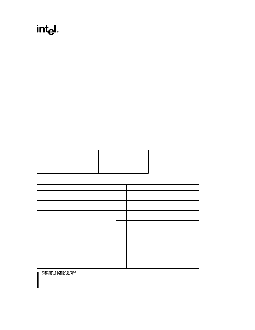
OPERATING CONDITIONS
Symbol
Parameter
Notes
Min
Max
Unit
§
C
T
A
Operating Temperature
0
70
V
CC
V
CC
Supply Voltage (10%)
5
4.50
5.50
V
V
CC
V
CC
Supply Voltage (5%)
5
4.75
5.25
V
DC CHARACTERISTICS
Symbol
Parameter
Notes
Min
Typ
Max
Unit
Test Condition
I
LI
Input Load Current
1
g
1.0
m
A
V
CC
e
V
CC
Max
V
IN
e
V
CC
or GND
V
CC
e
V
CC
Max
V
OUT
e
V
CC
or GND
V
CC
e
V
CC
Max
CE
Y
e
RP
Y
e
V
IH
V
CC
e
V
CC
Max
CE
Y
e
RP
Y
e
V
CC
g
0.2V
RP
Y
e
GND
g
0.2V
I
OUT
(RY/BY
Y
)
e
0 mA
V
CC
e
V
CC
Max, CE
Y
e
GND
f
e
8 MHz, I
OUT
e
0 mA
CMOS Inputs
I
LO
Output Leakage Current
1
g
10
m
A
I
CCS
V
CC
Standby Current
1, 3
1.0
2.0
mA
30
100
m
A
I
CCD
V
CC
Deep PowerDown
Current
1
0.20
1.2
m
A
I
CCR
V
CC
Read Current
1
20
35
mA
25
50
mA
V
CC
e
V
CC
Max, CE
Y
e
V
IL
f
e
8 MHz, I
OUT
e
0 mA
TTL Inputs
19
相關(guān)PDF資料 |
PDF描述 |
|---|---|
| PA28F008SC-120 | BYTE-WIDE SmartVoltage FlashFile MEMORY FAMILY 4, 8, AND 16 MBIT |
| PA34 | POWER OPERATIONAL AMPLIFIERS |
| PA44 | HIGH VOLTAGE POWER OPERATIONAL AMPLIFIER |
| PA7540JI-15 | PA7540 PEEL Array? Programmable Electrically Erasable Logic Array |
| PA7540JN-15 | PA7540 PEEL Array? Programmable Electrically Erasable Logic Array |
相關(guān)代理商/技術(shù)參數(shù) |
參數(shù)描述 |
|---|---|
| PA28F008SA85 | 制造商:Rochester Electronics LLC 功能描述: 制造商:Intel 功能描述: |
| PA28F008SA-85 | 制造商:INTEL 制造商全稱:Intel Corporation 功能描述:8-MBIT (1-MBIT x 8) FlashFileTM MEMORY |
| PA28F008SA-L200 | 制造商:未知廠家 制造商全稱:未知廠家 功能描述:x8 Flash EEPROM |
| PA28F008SA-L250 | 制造商:未知廠家 制造商全稱:未知廠家 功能描述:x8 Flash EEPROM |
| PA28F008SC-120 | 制造商:INTEL 制造商全稱:Intel Corporation 功能描述:BYTE-WIDE SmartVoltage FlashFile⑩ MEMORY FAMILY 4, 8, AND 16 MBIT |
發(fā)布緊急采購,3分鐘左右您將得到回復(fù)。