- 您現(xiàn)在的位置:買賣IC網(wǎng) > PDF目錄367741 > P80C557E6 (NXP Semiconductors N.V.) Single-chip 8-bit microcontroller(單片8位微控制器) PDF資料下載
參數(shù)資料
| 型號(hào): | P80C557E6 |
| 廠商: | NXP Semiconductors N.V. |
| 英文描述: | Single-chip 8-bit microcontroller(單片8位微控制器) |
| 中文描述: | 單芯片8位微控制器(單片8位微控制器) |
| 文件頁數(shù): | 40/64頁 |
| 文件大?。?/td> | 476K |
| 代理商: | P80C557E6 |
第1頁第2頁第3頁第4頁第5頁第6頁第7頁第8頁第9頁第10頁第11頁第12頁第13頁第14頁第15頁第16頁第17頁第18頁第19頁第20頁第21頁第22頁第23頁第24頁第25頁第26頁第27頁第28頁第29頁第30頁第31頁第32頁第33頁第34頁第35頁第36頁第37頁第38頁第39頁當(dāng)前第40頁第41頁第42頁第43頁第44頁第45頁第46頁第47頁第48頁第49頁第50頁第51頁第52頁第53頁第54頁第55頁第56頁第57頁第58頁第59頁第60頁第61頁第62頁第63頁第64頁
Philips Semiconductors
Product specification
P83C557E6/P80C557E6
Single-chip 8-bit microcontroller
1999 Mar 02
40
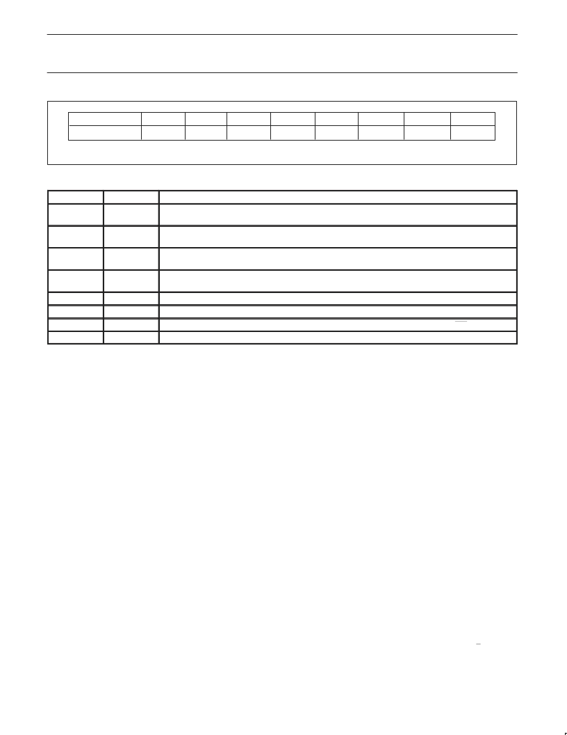
Figure 39. Power control register (PCON).
7
6
5
4
3
2
1
0
PCON (87H)
SMOD
ARD
RFI
WLE
GF1
GF0
PD
IDL
Table 39.
Description of PCON bits
SYMBOL
BIT
FUNCTION
SMOD
PCON.7
Double Baud rate bit. When set to logic 1 the baud rate is doubled when the serial port SIO0 is being used in
modes 1, 2, or 3.
ARD
PCON.6
AUX–RAM disable bit. When set to a 1 the internal 1280 bytes AUX–RAM is disabled, so that all
MOVX–Instructions access the external data memory – as it is with the standard PCB80C51.
RFI
PCON.5
Reduced radio frequency interference bit. When set to a 1 the toggling of ALE pin is prohibited. This bit is
cleared on RESET (see also sections Features (EMC) and Pinning).
WLE
PCON.4
Watchdog load enable. This flag must be set by software prior to loading timer T3 (watchdog timer). It is cleared
when timer T3 is loaded.
GF1
PCON.3
General-purpose flag bit
GF0
PCON.2
General-purpose flag bit
PD
PCON.1
Power-down bit. Setting this bit activates the power-down mode. It can only be set if input EW is high.
IDL
PCON.0
Idle Mode bit. Setting this bit activates the Idle Mode.
6.11
Two software–selectable modes of reduced power consumption are
implemented. These are the Idle Mode and the Power–down Mode.
Power Reduction Modes
Idle Mode operation permits the interrupt, serial ports and timer
blocks T0, T1 and T3 to function while the CPU is halted. The
following functions are switched off when the microcontroller enters
the Idle Mode:
CPU
(halted)
Timer 2
(stopped and reset)
PWM0, PWM1
(reset, output = HIGH)
ADC
(aborted if conversion in progress)
The following functions remain active during Idle Mode. These
functions may generate an interrupt or reset and thus terminate the
Idle Mode:
Timer 0, Timer 1, Timer 3 (Watchdog timer)
UART
I
2
C
External interrupt
Seconds Timer
In Power–down Mode the system clock is halted. If the PLL
oscillator is selected (SELXTAL1 = 0) and the RUN32 bit is set, the
32 kHz oscillator keeps running, otherwise it is stopped. If the
HF–oscillator (SELXTAL1 = 1) is selected, it is stopped after setting
the bit PD in the PCON register.
6.11.1
The modes Idle and Power–down are activated by software via the
Special Function Register PCON. Its hardware address is 87H.
Power Control Register
PCON is not bit addressable. The reset value of PCON is
(00000000).
6.11.2
The instruction that sets PCON.0 is the last instruction executed in
the normal operating mode before Idle Mode is activated. Once in
the Idle Mode, the CPU status is preserved in its entirety: the Stack
Pointer, Program Counter, Program Status Word, Accumulator, RAM
and all other registers maintain their data during Idle Mode. The
status of external pins during Idle Mode is shown in Table 40.
Idle Mode
There are three ways to terminate the Idle Mode:
Activation of any enabled interrupt X0, T0, X1, SEC, T1, S0 or S1
will cause PCON.0 to be cleared by hardware terminating Idle Mode
but only, if there is no interrupt in service with the same or higher
priority. The interrupt is serviced, and following return from interrupt
instruction RETI, the next instruction to be executed will be the one
which follows the instruction that wrote a logic 1 to PCON.0.
The flag bits GF0 and GF1 may be used to determine whether the
interrupt was received during normal execution or during Idle Mode.
For example, the instruction that writes to PCON.0 can also set or
clear one or both flag bits. When Idle Mode is terminated by an
interrupt, the service routine can examine the status of the flag bits.
The second way of terminating the Idle Mode is with an external
hardware reset. Since the oscillator is still running, the hardware
reset is required to be active for two machine cycles (24 HF
oscillator periods) to complete the reset operation if the HF oscillator
is selected.
When the PLL oscillator is selected a hardware reset of > 1
μ
sec
(but no longer than 10 ms) is required and the microcontroller will
typically restart within 63 msec after the reset has finished.
The third way of terminating the Idle Mode is by internal watchdog
reset. The microcontroller restarts after 3 machine cycles in all
cases.
相關(guān)PDF資料 |
PDF描述 |
|---|---|
| P89C58 | 80C51 8-bit microcontroller family 4K/8K/16K/32K Flash |
| P89C54X2 | 80C51 8-bit Flash microcontroller family |
| P89C54X2BA | 80C51 8-bit Flash microcontroller family |
| P89C54X2BBD | 80C51 8-bit Flash microcontroller family |
| P89C54X2BN | 80C51 8-bit Flash microcontroller family |
相關(guān)代理商/技術(shù)參數(shù) |
參數(shù)描述 |
|---|---|
| P80C557E6EBB | 制造商:PHILIPS 制造商全稱:NXP Semiconductors 功能描述:Single-chip 8-bit microcontroller |
| P80C557E6EFB | 制造商:PHILIPS 制造商全稱:NXP Semiconductors 功能描述:Single-chip 8-bit microcontroller |
| P80C557E8 | 制造商:PHILIPS 制造商全稱:NXP Semiconductors 功能描述:8 BIT MICROCONTROLLER |
| P80C557E8EFB | 制造商:未知廠家 制造商全稱:未知廠家 功能描述:8-Bit Microcontroller |
| P80C562 | 制造商:PHILIPS 制造商全稱:NXP Semiconductors 功能描述:8-bit microcontroller |
發(fā)布緊急采購,3分鐘左右您將得到回復(fù)。