- 您現(xiàn)在的位置:買賣IC網(wǎng) > PDF目錄361089 > NCN6000 (ON SEMICONDUCTOR) Compact Smart Card Interface IC(智能卡接口集成電路) PDF資料下載
參數(shù)資料
| 型號(hào): | NCN6000 |
| 廠商: | ON SEMICONDUCTOR |
| 英文描述: | Compact Smart Card Interface IC(智能卡接口集成電路) |
| 中文描述: | 緊湊型智能卡接口IC(智能卡接口集成電路) |
| 文件頁(yè)數(shù): | 23/36頁(yè) |
| 文件大?。?/td> | 358K |
| 代理商: | NCN6000 |
第1頁(yè)第2頁(yè)第3頁(yè)第4頁(yè)第5頁(yè)第6頁(yè)第7頁(yè)第8頁(yè)第9頁(yè)第10頁(yè)第11頁(yè)第12頁(yè)第13頁(yè)第14頁(yè)第15頁(yè)第16頁(yè)第17頁(yè)第18頁(yè)第19頁(yè)第20頁(yè)第21頁(yè)第22頁(yè)當(dāng)前第23頁(yè)第24頁(yè)第25頁(yè)第26頁(yè)第27頁(yè)第28頁(yè)第29頁(yè)第30頁(yè)第31頁(yè)第32頁(yè)第33頁(yè)第34頁(yè)第35頁(yè)第36頁(yè)
NCN6000
http://onsemi.com
23
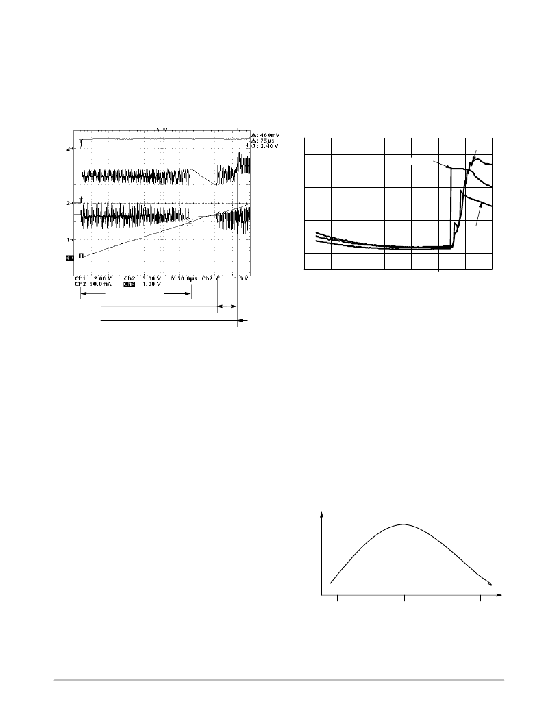
When the input voltage Vbat is lower than the
programmed CRD_VCC, the system operates under the
boost mode, providing the voltage regulation and current
limit to the smart card. In this mode, the external inductor,
typically 22 H, stores the energy to drive the +5.0 V card
supply from the external low voltage battery. The
oscillogram, Figure 18, depicts the DCDC behavior under
these two modes of operation.
Beside the DCDC converter, NMOS Q4 provides a low
impedance to ground during the Power Down sequence,
yielding the 250 s maximum switch time depicted in the
data sheet.
Figure 18. DCDC Operating Modes
Step Down Mode
CRD_VCC 5 V Step Up Mode
CRD_VCC
I
L
Ibat
DC Operating Current @ CRD_VCC = 5.0 V
0
1
2
3
4
5
6
7
8
2.5
3.0
3.5
4.0
4.5
5.0
5.5
6.0
Vbat (V)
I
25
°
C
85
°
C
POWER_ON
Figure 19. Typical DC Operating Current
25
°
C
When the input voltage Vbat is higher than the
programmed CRD_VCC, the system operates under a step
down mode, yielding the voltage regulation and current
limit identical to the boost mode. In this case, the builtin
structure turns Off Q1 and inverts the Q2 substrate bias to
control the current flowing to the load.These operations are
fully automatic and transparent for the end user.
The High and Low limits of the current flowing into the
external inductor L1 are sensed by the operational amplifier
U1 associated with the internal shunt R1. Since this shunt
resistor is located on the hot side of the inductor, the device
reads both the charge and discharge of the inductor,
providing a clean operation of the converter.
In order to optimize the DCDC power conversion
efficiency, it is recommended to use external inductor with
R < 2.0 .
The output capacitor C1 stores the energy coming from the
converter and smooths the CRD_VCC voltage applied to the
external card. At this point, care must be observed, beside the
micro farad value, to select the right type of capacitor.
According to the capacitor’s manufacturers, the internal ESR
can range from a low 10 m to more than 3.0 , thus yielding
high losses during the DCDC operation, depending upon the
technology used to build the capacitor.
The standard electrolytic capacitors have the low cost
advantage for a relative high micro farad value, but have
poor tolerance, high leakage current and high ESR.
The tantalum type brings much lower leakage current
together with high capacity value per volume, but cost can
be an issue and ESR is rarely better than 500 m .
The new ceramic type have a very low leakage together
with ESR in the 50 m range, but value above 10 F are
relatively rare. Moreover, depending upon the low cost
ceramic material used to build these capacitors, the thermal
coefficient can be very bad, as depicted in Figure 20. The
X7R type is highly recommended to achieve low voltage
ripple.
Figure 20. Typical Y7R Ceramic Type Value as a
Function of the Temperature.
100%
25
°
C
+25
°
C
+85
°
C
15%
相關(guān)PDF資料 |
PDF描述 |
|---|---|
| NCN6001DTBR2 | Compact Smart Card Interface IC |
| NCN6001 | Compact Smart Card Interface IC |
| NCN6004AFTBR2 | Dual SAM/SIM Interface Integrated Circuit |
| NCN6004A | Dual SAM/SIM Interface Integrated Circuit |
| NCN6010DTBR2 | SIM Card Supply and Level Shifter |
相關(guān)代理商/技術(shù)參數(shù) |
參數(shù)描述 |
|---|---|
| NCN6000/D | 制造商:未知廠家 制造商全稱:未知廠家 功能描述:Compact Smart Card Interface IC |
| NCN6000DTB | 功能描述:輸入/輸出控制器接口集成電路 2.7V POS/ATM Smart RoHS:否 制造商:Silicon Labs 產(chǎn)品: 輸入/輸出端數(shù)量: 工作電源電壓: 最大工作溫度:+ 85 C 最小工作溫度:- 40 C 安裝風(fēng)格:SMD/SMT 封裝 / 箱體:QFN-64 封裝:Tray |
| NCN6000DTBG | 功能描述:輸入/輸出控制器接口集成電路 2.7V POS/ATM Smart Card Interface RoHS:否 制造商:Silicon Labs 產(chǎn)品: 輸入/輸出端數(shù)量: 工作電源電壓: 最大工作溫度:+ 85 C 最小工作溫度:- 40 C 安裝風(fēng)格:SMD/SMT 封裝 / 箱體:QFN-64 封裝:Tray |
| NCN6000DTBR2 | 功能描述:輸入/輸出控制器接口集成電路 2.7V POS/ATM Smart RoHS:否 制造商:Silicon Labs 產(chǎn)品: 輸入/輸出端數(shù)量: 工作電源電壓: 最大工作溫度:+ 85 C 最小工作溫度:- 40 C 安裝風(fēng)格:SMD/SMT 封裝 / 箱體:QFN-64 封裝:Tray |
| NCN6000DTBR2G | 功能描述:輸入/輸出控制器接口集成電路 2.7V POS/ATM Smart Card Interface RoHS:否 制造商:Silicon Labs 產(chǎn)品: 輸入/輸出端數(shù)量: 工作電源電壓: 最大工作溫度:+ 85 C 最小工作溫度:- 40 C 安裝風(fēng)格:SMD/SMT 封裝 / 箱體:QFN-64 封裝:Tray |
發(fā)布緊急采購(gòu),3分鐘左右您將得到回復(fù)。