- 您現(xiàn)在的位置:買賣IC網(wǎng) > PDF目錄25635 > MQ80C32E-30/883 (TEMIC SEMICONDUCTORS) 8-BIT, 30 MHz, MICROCONTROLLER, CQFP44 PDF資料下載
參數(shù)資料
| 型號: | MQ80C32E-30/883 |
| 廠商: | TEMIC SEMICONDUCTORS |
| 元件分類: | 微控制器/微處理器 |
| 英文描述: | 8-BIT, 30 MHz, MICROCONTROLLER, CQFP44 |
| 文件頁數(shù): | 22/198頁 |
| 文件大?。?/td> | 4822K |
| 代理商: | MQ80C32E-30/883 |
第1頁第2頁第3頁第4頁第5頁第6頁第7頁第8頁第9頁第10頁第11頁第12頁第13頁第14頁第15頁第16頁第17頁第18頁第19頁第20頁第21頁當(dāng)前第22頁第23頁第24頁第25頁第26頁第27頁第28頁第29頁第30頁第31頁第32頁第33頁第34頁第35頁第36頁第37頁第38頁第39頁第40頁第41頁第42頁第43頁第44頁第45頁第46頁第47頁第48頁第49頁第50頁第51頁第52頁第53頁第54頁第55頁第56頁第57頁第58頁第59頁第60頁第61頁第62頁第63頁第64頁第65頁第66頁第67頁第68頁第69頁第70頁第71頁第72頁第73頁第74頁第75頁第76頁第77頁第78頁第79頁第80頁第81頁第82頁第83頁第84頁第85頁第86頁第87頁第88頁第89頁第90頁第91頁第92頁第93頁第94頁第95頁第96頁第97頁第98頁第99頁第100頁第101頁第102頁第103頁第104頁第105頁第106頁第107頁第108頁第109頁第110頁第111頁第112頁第113頁第114頁第115頁第116頁第117頁第118頁第119頁第120頁第121頁第122頁第123頁第124頁第125頁第126頁第127頁第128頁第129頁第130頁第131頁第132頁第133頁第134頁第135頁第136頁第137頁第138頁第139頁第140頁第141頁第142頁第143頁第144頁第145頁第146頁第147頁第148頁第149頁第150頁第151頁第152頁第153頁第154頁第155頁第156頁第157頁第158頁第159頁第160頁第161頁第162頁第163頁第164頁第165頁第166頁第167頁第168頁第169頁第170頁第171頁第172頁第173頁第174頁第175頁第176頁第177頁第178頁第179頁第180頁第181頁第182頁第183頁第184頁第185頁第186頁第187頁第188頁第189頁第190頁第191頁第192頁第193頁第194頁第195頁第196頁第197頁第198頁
118
8111C–MCU Wireless–09/09
AT86RF231
Note:
During reset procedure, see Section 7.1.2.8 “RESET State” on page 37, register bits CLKM_CTRL are
shadowed. Although the clock setting of CLKM remains after reset, a read access to register bits
CLKM_CTRL delivers the reset value 1. For that reason it is recommended to write the previous
configuration (before reset) to register bits CLKM_CTRL (after reset) to align the radio transceiver
behavior and register configuration. Otherwise the CLKM clock rate is set back to the reset value (1
MHz) after the next SLEEP cycle.
For example, if the CLKM clock rate is configured to 16 MHz the CLKM clock rate remains at 16 MHz
after a reset, however the register bits CLKM_CTRL are set back to 1. Since CLKM_SHA_SEL reset
value is 1, the CLKM clock rate changes to 1 MHz after the next SLEEP cycle if the CLKM_CTRL
setting is not updated after reset.
9.6.5
Register Description
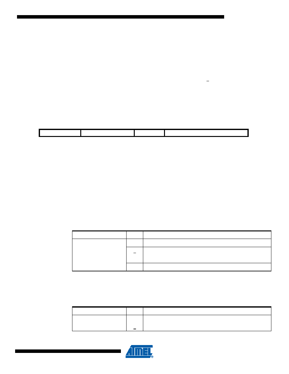
Register 0x03 (TRX_CTRL_0):
The TRX_CTRL_0 register controls the drive current of the digital output pads and the CLKM
clock rate. It is recommended to use the lowest value for the drive current to reduce the current
consumption and the emission of signal harmonics.
Bit [7:6] - PAD_IO
Bit [5:6] - PAD_IO_CLKM
These register bits set the output driver current of pin CLKM. It is recommended to reduce the
current capability to PAD_IO_CLKM = 0 (2 mA) if possible. This reduces power consumption
and spurious emissions.
Bit 3 - CLKM_SHA_SEL
Register bit CLKM_SHA_SEL defines if a new clock rate, defined by CLKM_CTRL, is set imme-
diately or after the next SLEEP cycle.
Bit
76
5
4
3
2
1
0
+0x03
PAD_IO
PAD_IO_CLKM
CLKM_SHA_SEL
CLKM_CTRL
TRX_CTRL_0
Read/Write
R/W
Initial Value
0
1
0
1
Table 9-12.
CLKM Driver Strength
Register Bit
Value
Description
PAD_IO_CLKM
0
2 mA
1
4 mA
26 mA
38 mA
Table 9-13.
CLKM Clock Rate Update Scheme
Register Bit
Value
Description
CLKM_SHA_SEL
0
CLKM clock rate change appears immediately
1
CLKM clock rate change appears after SLEEP cycle
相關(guān)PDF資料 |
PDF描述 |
|---|---|
| MR80C52CXXX-16/883R | 8-BIT, MROM, 16 MHz, MICROCONTROLLER, CQCC44 |
| MR80C52TXXX-16SB | 8-BIT, MROM, 16 MHz, MICROCONTROLLER, CQCC44 |
| MD83C154TXXX-L16P883D | 8-BIT, MROM, 16 MHz, MICROCONTROLLER, CDIP40 |
| MD83C154XXX-L16P883D | 8-BIT, MROM, 16 MHz, MICROCONTROLLER, CDIP40 |
| MQ80C32E-16SB | 8-BIT, 16 MHz, MICROCONTROLLER, CQFP44 |
相關(guān)代理商/技術(shù)參數(shù) |
參數(shù)描述 |
|---|---|
| MQ82370-20 | 制造商:Rochester Electronics LLC 功能描述:- Bulk |
| MQ8238020 | 制造商:Intel 功能描述:CONTROLLER: OTHER |
| MQ82380-20 | 制造商:Rochester Electronics LLC 功能描述:- Bulk |
| MQ82380-20/R | 制造商:Rochester Electronics LLC 功能描述: |
| MQ82592 | 制造商:Rochester Electronics LLC 功能描述:- Bulk |
發(fā)布緊急采購,3分鐘左右您將得到回復(fù)。