- 您現(xiàn)在的位置:買賣IC網(wǎng) > PDF目錄369917 > MIG10J503 (Toshiba Corporation) TOSHIBA INTELLIGENT POWER MODULE PDF資料下載
參數(shù)資料
| 型號: | MIG10J503 |
| 廠商: | Toshiba Corporation |
| 英文描述: | TOSHIBA INTELLIGENT POWER MODULE |
| 中文描述: | 東芝智能功率模塊 |
| 文件頁數(shù): | 4/9頁 |
| 文件大小: | 112K |
| 代理商: | MIG10J503 |

TENTATIVE
MIG10J503
TOSHIBA CONFIDENTIAL
4
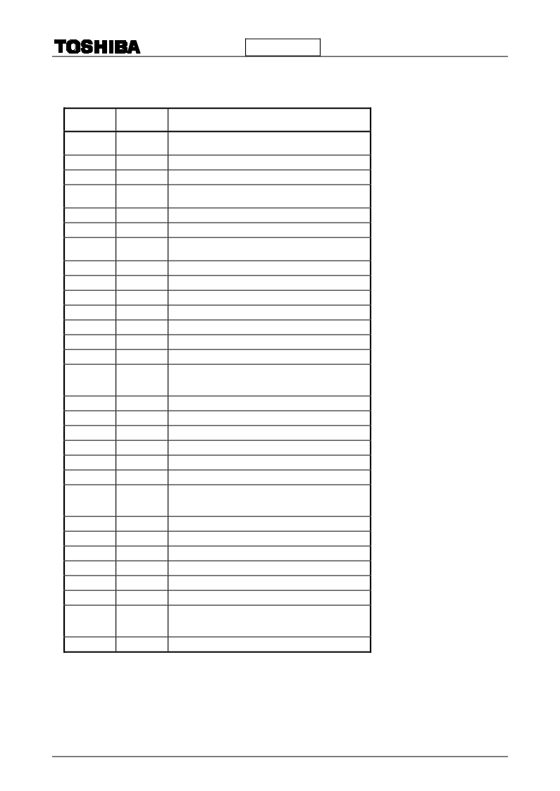
Pin Description
Pin No.
Symbol
Pin Description
1
PGND U
U-Phase Power Ground pin
resistor between this pin and SGND U pin)
Connect a current detecting
2
U
U-Phase output pin
3
V
BB
U
U-Phase high-voltage power supply pin
4
PGND V
V-Phase Power Ground pin
resistor between this pin and SGND V pin)
Connect a current detecting
5
V
V-Phase output pin
6
V
BB
V
V-Phase high-voltage power supply pin
7
PGND W
W-Phase Power Ground pin
resistor between this pin and SGND W pin)
Connect a current detecting
8
W
W-Phase output pin
9
V
BB
W
W-Phase high-voltage power supply pin
10
C W
W-Phase bootstrap capacitor connecting pin(-)
11
BS W
W-Phase bootstrap capacitor connecting pin(+)
12
SGND W
W-Phase Signal Ground pin
13
IN Z
W-Phase low-side input pin(Negative logic)
14
IN W
W-Phase high-side input pin(Negative logic)
15
FO W
W-Phase Diagnosis output pin(open drain output. Wired or
connection can be performed with the Diagnosis output pin
of other Phase.)
16
V
CC
W
W-Phase control power supply (+15V typ.)
17
C V
V-Phase bootstrap capacitor connecting pin(-)
18
BS V
V-Phase bootstrap capacitor connecting pin(+)
19
SGND V
V-Phase Signal Ground pin
20
IN Y
V-Phase low-side input pin (Negative logic)
21
IN V
V-Phase high-side input pin (Negative logic)
22
FO V
V-Phase Diagnosis output pin(open drain output. Wired or
connection can be performed with the Diagnosis output pin
of other Phase.)
23
V
CC
V
V-Phase control power supply (+15V typ.)
24
C U
U-Phase bootstrap capacitor connecting pin (-)
25
BS U
U-Phase bootstrap capacitor connecting pin (+)
26
SGND U
U-Phase Signal Ground pin
27
IN X
U-Phase low-side input pin (Negative logic)
28
IN U
U-Phase high-side input pin (Negative logic)
29
FO U
U-Phase Diagnosis output pin(open drain output. Wired or
connection can be performed with the Diagnosis output pin
of other Phase.)
30
V
CC
U
U-Phase control power supply (+15V typ.)
相關(guān)PDF資料 |
PDF描述 |
|---|---|
| MIG150Q201H | TOSHIBA Intelligent Power Module Silicon N Channel IGBT |
| MIG150Q6CMB1X | High Power Switching Applications Motor Control Applications |
| MIG200J201H | Silicon N channel IGBT(N溝道絕緣柵雙極型晶體管) |
| MIG20J901H | INTEGRATED GTR MODULE |
| MIG20J902H | INTEGRATED GTR MODULE |
相關(guān)代理商/技術(shù)參數(shù) |
參數(shù)描述 |
|---|---|
| MIG10Q805H | 制造商:TOSHIBA 制造商全稱:Toshiba Semiconductor 功能描述:N CHANNEL IGBT (HIGH POWER SWITCHING, MOTOR CONTROL APPLICATIONS) |
| MIG10Q806H | 制造商:Toshiba 功能描述:_ |
| MIG10Q906H | 制造商:Toshiba America Electronic Components 功能描述: |
| MIG150J202H | 制造商:TOSHIBA 制造商全稱:Toshiba Semiconductor 功能描述:N CHANNEL IGBT (HIGH POWER SWITCHING, MOTOR CONTROL APPLICATIONS) |
| MIG150J6CSB1W | 制造商:MITSUBISHI 制造商全稱:Mitsubishi Electric Semiconductor 功能描述:High Power Switching Applications Motor Control Applications |
發(fā)布緊急采購,3分鐘左右您將得到回復(fù)。