- 您現(xiàn)在的位置:買賣IC網(wǎng) > PDF目錄69032 > MCV14AI/SL 8-BIT, FLASH, 20 MHz, RISC MICROCONTROLLER, PDSO14 PDF資料下載
參數(shù)資料
| 型號: | MCV14AI/SL |
| 元件分類: | 微控制器/微處理器 |
| 英文描述: | 8-BIT, FLASH, 20 MHz, RISC MICROCONTROLLER, PDSO14 |
| 封裝: | 3.90 MM, PLASTIC, SOIC-4 |
| 文件頁數(shù): | 49/84頁 |
| 文件大小: | 1007K |
| 代理商: | MCV14AI/SL |
第1頁第2頁第3頁第4頁第5頁第6頁第7頁第8頁第9頁第10頁第11頁第12頁第13頁第14頁第15頁第16頁第17頁第18頁第19頁第20頁第21頁第22頁第23頁第24頁第25頁第26頁第27頁第28頁第29頁第30頁第31頁第32頁第33頁第34頁第35頁第36頁第37頁第38頁第39頁第40頁第41頁第42頁第43頁第44頁第45頁第46頁第47頁第48頁當(dāng)前第49頁第50頁第51頁第52頁第53頁第54頁第55頁第56頁第57頁第58頁第59頁第60頁第61頁第62頁第63頁第64頁第65頁第66頁第67頁第68頁第69頁第70頁第71頁第72頁第73頁第74頁第75頁第76頁第77頁第78頁第79頁第80頁第81頁第82頁第83頁第84頁
2009 Microchip Technology Inc.
Preliminary
DS41338B-page 51
MCV14A
8.1.6
ANALOG CONVERSION RESULT
REGISTER
The ADRES register contains the results of the last
conversion. These results are present during the
sampling period of the next analog conversion process.
After the sampling period is over, ADRES is cleared
(= 0). A ‘leading one’ is then right shifted into the
ADRES to serve as an internal conversion complete
bit. As each bit weight, starting with the MSB, is
converted, the leading one is shifted right and the
converted bit is stuffed into ADRES. After a total of 9
right shifts of the ‘leading one’ have taken place, the
conversion is complete; the ‘leading one’ has been
shifted out and the GO/DONE bit is cleared.
If the GO/DONE bit is cleared in software during a
conversion, the conversion stops. The data in ADRES
is the partial conversion result. This data is valid for the
bit weights that have been converted. The position of
the ‘leading one’ determines the number of bits that
have been converted. The bits that were not converted
before the GO/DONE was cleared are unrecoverable.
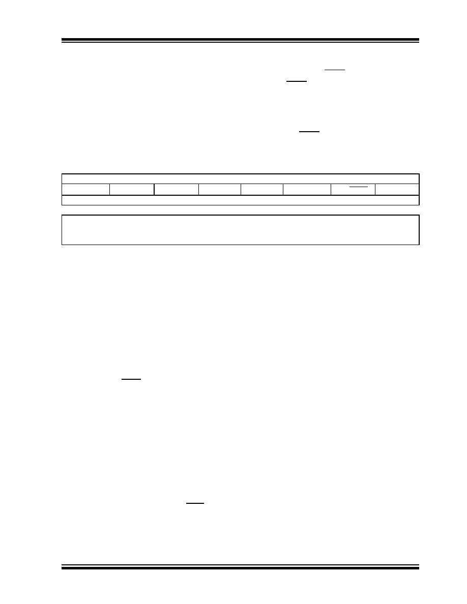
REGISTER 8-1:
ADCON0: A/D CONTROL REGISTER
R/W-1
R/W-0
ANS1
ANS0
ADCS1
ADCS0
CHS1
CHS0
GO/DONE
ADON
bit 7
bit 0
Legend:
R = Readable bit
W = Writable bit
U = Unimplemented bit, read as ‘0’
-n = Value at POR
‘1’ = Bit is set
‘0’ = Bit is cleared
x = Bit is unknown
bit 7-6
ANS<1:0>: ADC Analog Input Pin Select bits(1), (2), (5)
00
= No pins configured for analog input
01
= AN2 configured as an analog input
10
= AN2 and AN0 configured as analog inputs
11
= AN2, AN1 and AN0 configured as analog inputs
bit 5-4
ADCS<1:0>: ADC Conversion Clock Select bits
00
= FOSC/16
01
= FOSC/8
10
= FOSC/4
11
= INTOSC/4
bit 3-2
CHS<1:0>: ADC Channel Select bits(3, 5)
00
= Channel AN0
01
= Channel AN1
10
= Channel AN2
11
= 0.6V absolute voltage reference
bit 1
GO/DONE: ADC Conversion Status bit(4)
1
= ADC conversion in progress. Setting this bit starts an ADC conversion cycle. This bit is automatically cleared
by hardware when the ADC is done converting.
0
= ADC conversion completed/not in progress. Manually clearing this bit while a conversion is in process termi-
nates the current conversion.
bit 0
ADON: ADC Enable bit
1
= ADC module is operating
0
= ADC module is shut-off and consumes no power
Note 1:
When the ANS bits are set, the channels selected will automatically be forced into Analog mode, regardless of the pin
function previously defined. The only exception to this is the comparator, where the analog input to the comparator and
the ADC will be active at the same time. It is the users responsibility to ensure that the ADC loading on the comparator
input does not affect their application.
2:
The ANS<1:0> bits are active regardless of the condition of ADON.
3:
CHS<1:0> bits default to 11 after any Reset.
4:
If the ADON bit is clear, the GO/DONE bit cannot be set.
5:
C1OUT, when enabled, overrides AN2.
相關(guān)PDF資料 |
PDF描述 |
|---|---|
| MCV14ATI/SL | 8-BIT, FLASH, 20 MHz, RISC MICROCONTROLLER, PDSO14 |
| MCV14AI/P | 8-BIT, FLASH, 20 MHz, RISC MICROCONTROLLER, PDIP14 |
| MD8031AHB883B | 8-BIT, 12 MHz, MICROCONTROLLER, CDIP40 |
| MD8255A | 24 I/O, PIA-GENERAL PURPOSE, PDIP40 |
| MD82C52-/883 | 1 CHANNEL(S), 1M bps, SERIAL COMM CONTROLLER, CDIP28 |
相關(guān)代理商/技術(shù)參數(shù) |
參數(shù)描述 |
|---|---|
| MCV15/10-GF-381 | 制造商:Phoenix Contact 功能描述:HEADER PCB VERTICAL 3.81MM 10WAY |
| MCV15/2-GF-381 | 制造商:Phoenix Contact 功能描述:HEADER PCB VERTICAL 3.81MM 2WAY |
| MCV15/3-GF-381 | 制造商:Phoenix Contact 功能描述:HEADER PCB VERTICAL 3.81MM 3WAY |
| MCV15/4-GF-381 | 制造商:Phoenix Contact 功能描述:HEADER PCB VERTICAL 3.81MM 4WAY |
| MCV15/5-GF-381 | 制造商:Phoenix Contact 功能描述:HEADER PCB VERTICAL 3.81MM 5WAY |
發(fā)布緊急采購,3分鐘左右您將得到回復(fù)。