- 您現(xiàn)在的位置:買賣IC網(wǎng) > PDF目錄69021 > MB90F949APF MICROCONTROLLER, PQFP100 PDF資料下載
參數(shù)資料
| 型號(hào): | MB90F949APF |
| 元件分類: | 微控制器/微處理器 |
| 英文描述: | MICROCONTROLLER, PQFP100 |
| 封裝: | 14 X 20 MM, 3.35 MM HEIGHT, 0.65 MM PITCH, PLASTIC, QFP-100 |
| 文件頁數(shù): | 28/57頁 |
| 文件大小: | 1586K |
| 代理商: | MB90F949APF |
第1頁第2頁第3頁第4頁第5頁第6頁第7頁第8頁第9頁第10頁第11頁第12頁第13頁第14頁第15頁第16頁第17頁第18頁第19頁第20頁第21頁第22頁第23頁第24頁第25頁第26頁第27頁當(dāng)前第28頁第29頁第30頁第31頁第32頁第33頁第34頁第35頁第36頁第37頁第38頁第39頁第40頁第41頁第42頁第43頁第44頁第45頁第46頁第47頁第48頁第49頁第50頁第51頁第52頁第53頁第54頁第55頁第56頁第57頁
SINGLE-CHIP 8-BIT CMOS MICROCOMPUTER
7544 Group
MITSUBISHI MICROCOMPUTERS
34
PRELIMINAR
Y
Notice:
This
is not
a final
specification.
Some
parametric
limits
are
subject
to change.
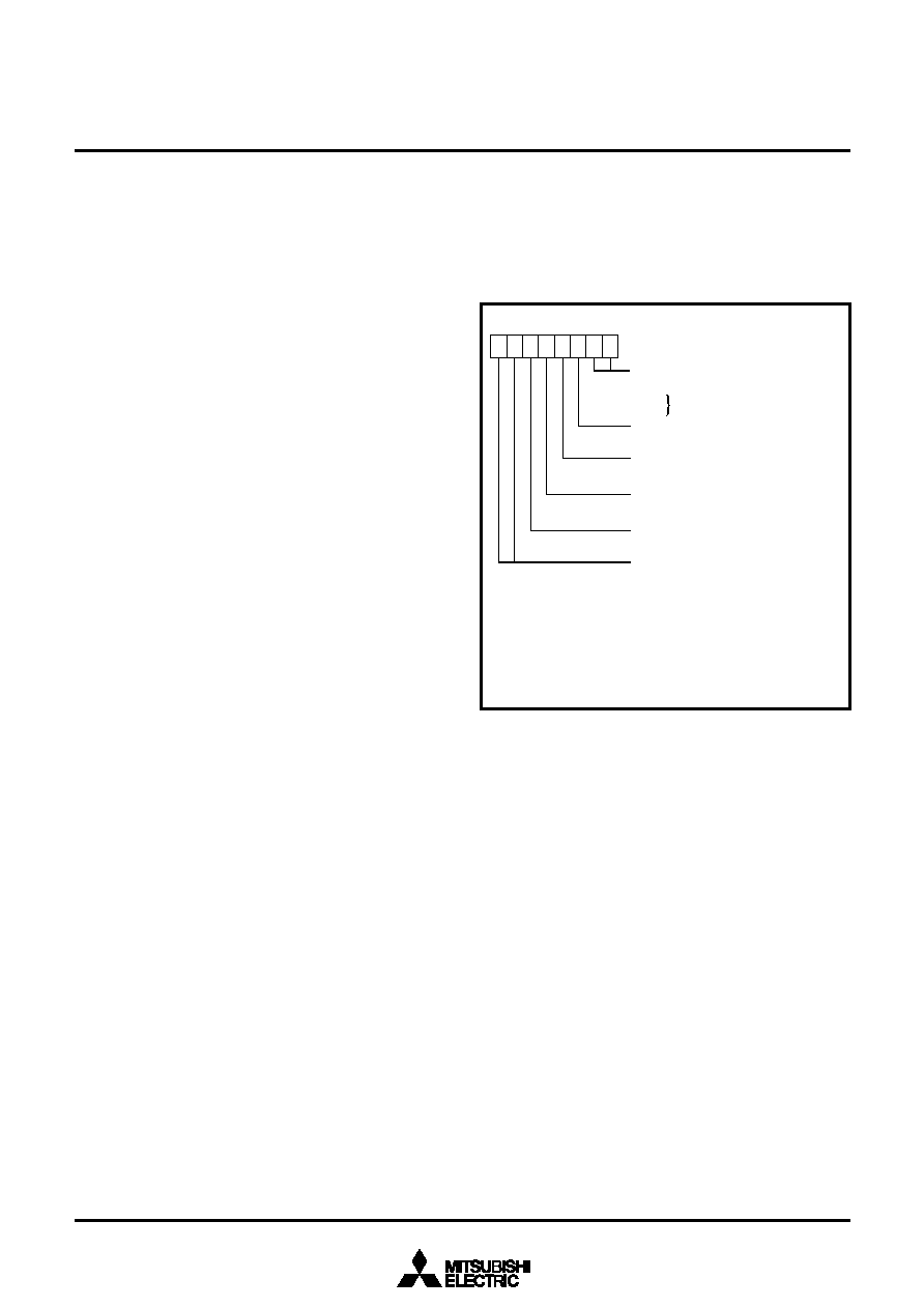
Fig. 42 Structure of CPU mode register
(1) Oscillation control
Stop mode
When the STP instruction is executed, the internal clock
φ stops at
an “H” level and the XIN oscillator stops. At this time, timer 1 is set
to “0116” and prescaler 1 is set to “FF16” when the oscillation sta-
bilization time set bit after release of the STP instruction is “0”. On
the other hand, timer 1 and prescaler 1 are not set when the
above bit is “1”. Accordingly, set the wait time fit for the oscillation
stabilization time of the oscillator to be used. Single selected by
the timer1countsource selection bit is connected to the input of
prescaler 1. When an external interrupt is accepted, oscillation is
restarted but the internal clock
φ remains at “H” until timer 1
underflows. As soon as timer 1 underflows, the internal clock
φ is
supplied. This is because when a ceramic / quartz-crystal oscilla-
tor is used, some time is required until a start of oscillation. In
case oscillation is restarted by reset, no wait time is generated. So
______
apply an “L” level to the RESET pin while oscillation becomes
stable.
Also, the STP instruction cannot be used while CPU is operating
by a ring oscillator.
Wait mode
If the WIT instruction is executed, the internal clock
φ stops at an
“H” level, but the oscillator does not stop. The internal clock re-
starts if a reset occurs or when an interrupt is received. Since the
oscillator does not stop, normal operation can be started immedi-
ately after the clock is restarted. To ensure that interrupts will be
received to release the STP or WIT state, interrupt enable bits
must be set to “1” before the STP or WIT instruction is executed.
s Notes on clock generating circuit
For use with the oscillation stabilization set bit after release of the
STP instruction set to “1”, set values in timer 1 and prescaler 1 af-
ter fully appreciating the oscillation stabilization time of the
oscillator to be used.
Switch of ceramic / quartz-crystal and RC oscillations
After releasing reset the operation starts by starting a built-in ring
oscillator. Then, a ceramic / quartz-crystal oscillation or an RC os-
cillation is selected by setting bit 5 of the CPU mode register.
Double-speed mode
When a ceramic / quartz-cfystal oscillation is selected, a double-
speed mode can be used. Do not use it when an RC oscillation is
selected.
CPU mode register
Bits 5, 1 and 0 of CPU mode register are used to select oscillation
mode and to control operation modes of the microcomputer. In or-
der to prevent the dead-lock by error-writing (ex. program
run-away), these bits can be rewritten only once after releasing re-
set. After rewriting it is disable to write any data to the bit. (The
emulator MCU “M37544RSS” is excluded.)
Also, when the read-modify-write instructions (SEB, CLB) are ex-
ecuted to bits 2 to 4, 6 and 7, bits 5, 1 and 0 are locked.
Oscillation mode selection bit (Note 1)
0 : Ceramic / quartz-crystal oscillation
1 : RC oscillation
CPU mode register
(CPUM: address 003B16, initial value: 8016)
Stack page selection bit
0 : 0 page
1 : 1 page
Clock division ratio selection bits
b7 b6
0
0 : f(
φ) = f(XIN)/2 (High-speed mode)
0
1 : f(
φ) = f(XIN)/8 (Middle-speed mode)
1
0 : applied from ring oscillator
1
1 : f(
φ) = f(XIN) (Double-speed mode)(Note 2)
Ring oscillator oscillation control bit
0 : Ring oscillator oscillation enabled
1 : Ring oscillator oscillation stop
XIN oscillation control bit
0 : Ceramic / quartz-crystal or RC oscillation enabled
1 : Ceramic / quartz-crystal or RC oscillation stop
Processor mode bits (Note 1)
b1 b0
0
0 Single-chip mode
0
1
0
1
Not available
b7
b0
2: These bits are used only when a ceramic / quartz-crystal oscillation is selected.
Note 1: The bit can be rewritten only once after releasing reset. After rewriting
it is disable to write any data to the bit. However, by reset the bit is
initialized and can be rewritten, again.
(It is not disable to write any data to the bit for emulator MCU
“M37544RSS”.)
Do not use these when an RC oscillation is selected.
Clock division ratio, XIN oscillation control, ring oscillator control
The state transition shown in Fig. 46 can be performed by setting
the clock division ratio selection bits (bits 7 and 6), XIN oscillation
control bit (bit 4), ring oscillator oscillation control bit (bit 3) of CPU
mode register. Be careful of notes on use in Fig. 46.
相關(guān)PDF資料 |
PDF描述 |
|---|---|
| MB90947APF | MICROCONTROLLER, PQFP100 |
| MB90F947PF | 16-BIT, FLASH, 24 MHz, MICROCONTROLLER, PQFP100 |
| MB90F949PF | 16-BIT, FLASH, 24 MHz, MICROCONTROLLER, PQFP100 |
| MB90F967SPMT | 16-BIT, FLASH, 24 MHz, MICROCONTROLLER, PQFP48 |
| MB90P214PF | 16-BIT, OTPROM, 16 MHz, MICROCONTROLLER, PQFP80 |
相關(guān)代理商/技術(shù)參數(shù) |
參數(shù)描述 |
|---|---|
| MB90F962SPMCR-GE1 | 制造商:FUJITSU 功能描述:IC MCU 16BIT 16LX 48LQFP |
| MB90F962SPMCR-G-JNE1 | 制造商:FUJITSU 功能描述: |
| MB90V340A-102CR | 制造商:FUJITSU 功能描述: |
| MB-910 | 制造商:Circuit Test 功能描述:BREADBOARD WIRING KIT - 350 PCS |
| MB9100100 | 制造商:COM/DUO 功能描述:FAN 4-6WKS |
發(fā)布緊急采購,3分鐘左右您將得到回復(fù)。