- 您現(xiàn)在的位置:買賣IC網(wǎng) > PDF目錄9751 > MAX19005CCS+ (Maxim Integrated Products)IC DCL QUAD 300MHZ ATE 80TQFP PDF資料下載
參數(shù)資料
| 型號(hào): | MAX19005CCS+ |
| 廠商: | Maxim Integrated Products |
| 文件頁數(shù): | 12/25頁 |
| 文件大?。?/td> | 0K |
| 描述: | IC DCL QUAD 300MHZ ATE 80TQFP |
| 標(biāo)準(zhǔn)包裝: | 119 |
| 系列: | ATE |
| 邏輯類型: | 比較器, 驅(qū)動(dòng)器 |
| 電源電壓: | -1 V ~ 5.2 V |
| 位數(shù): | 4 |
| 工作溫度: | 0°C ~ 70°C |
| 安裝類型: | * |
| 封裝/外殼: | * |
| 供應(yīng)商設(shè)備封裝: | * |
| 包裝: | * |
Maxim Integrated Products 2
MAX19005
Quad, Ultra-Low-Power,
200Mbps ATE Drivers/Comparators
VDD to GND..........................................................-0.3V to +9.4V
VSS to GND ........................................................-6.25V to +0.3V
VDD - VSS ...................................................................... +15.65V
VL to GND ...............................................................-0.3V to +5V
DHV_, DLV_ to GND with
Integrated Pin Switch Off ................VSS - 0.3V to VDD + 0.3V
DHV_, DLV_ to GND with
Integrated Pin Switch On ........... VSSSW - 0.3V to VDD + 0.3V
DATA_, RCV_, VBBI to GND....................................-0.3V to +5V
LDV_ to GND.................................. VSSSW - 0.3V to VDD + 0.3V
CHV_, CLV_ COMPHI, COMPLO
to GND.............................................VSS - 0.3V to VDD + 0.3V
CMPH_, CMPL_, VBBO to GND ..............................-0.3V to VDD
LD, DIN, SCLK, CS, SWEN to GND. ....................... -0.3V to +VL
CHV_, CLV_ to DUT_ with Integrated Pin Switch On..............8V
DUT_ to GND with Integrated Pin Switch Off…VSSSW to VDDSW
DUT_ to GND with Integrated Pin Switch On…... VSSSW to VDD
FORCE, SENSE, PMU_ to GND ...................... VSSSW to VDDSW
VDDSW to VSSSW................................................................ +27V
VDDSW to VSS………………………………………... ……+31.35V
VDDSW to GND...................................................-0.3V to +26.1V
VSSSW to GND………………………………………-2.4V to +0.3V
DUT_, CMPH_, CMPL_ Short-Circuit Duration..........Continuous
DOUT to GND ......................................................... -0.3V to +VL
TEMP to GND..........................................................-0.3V to VDD
TEMP Short-Circuit Duration .....................................Continuous
PMU Force Switch Continuous Current .......................... ±35mA
PMU Force Switch Peak Current................................... ±160mA
PMU Sense Switch Continuous Current........................... ±1mA
PMU Sense Switch Peak Current.................................... ±30mA
All Digital Inputs .............................................................. ±30mA
Continuous Power Dissipation (TA = +70°C)
TQFP (derate 35.7mW/°C above +70°C) ...................2857mW
Storage Temperature Range............................ -65°C to +150°C
Junction Temperature .....................................................+150°C
Lead Temperature (soldering, 10s) ................................+300°C
Soldering Temperature (reflow) ......................................+260°C
ABSOLUTE MAXIMUM RATINGS
Stresses beyond those listed under “Absolute Maximum Ratings” may cause permanent damage to the device. These are stress ratings only, and functional opera-
tion of the device at these or any other conditions beyond those indicated in the operational sections of the specifications is not implied. Exposure to absolute
maximum rating conditions for extended periods may affect device reliability.
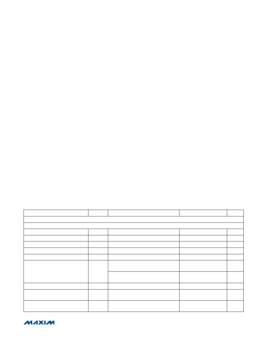
ELECTRICAL CHARACTERISTICS
(VDD = +8V, VSS = -5V, VL = +3V, VDDSW = +24.6V, VSSSW = -1.25V, VCOMPHI = +1V, VCOMPLO = 0V, VLDV__= 0V, LOAD EN
LOW_ = LOAD EN HIGH_ = 0, SWEN = 1, TJ = +70°C with an accuracy of ±15NC. Specification compliance with supply and
temperature variations is verified by guard-banding mean shifts of characterization data, unless otherwise noted. All temperature
coefficients measured at TJ = +50°C to +90°C, unless otherwise noted.) (Note 1)
PARAMETER
SYMBOL
CONDITIONS
MIN
TYP
MAX
UNITS
DRIVER (all specifications apply when DUT = DHV or DUT = DLV)
DC CHARACTERISTICS (RDUT R 10MI, unless otherwise noted)
Voltage Range
-1.0
+5.2
V
Gain
Measured at 0V and +3V
0.995
1
1.005
V/V
Gain Temperature Coefficient
50
ppm/NC
Offset
VDHV_ = +2V, VDLV_ = 0V
Q
10
mV
Offset Temperature Coefficient
VDHV_ = +1.5V
Q
250
F
V/NC
Power-Supply Rejection Ratio
PSRR
VDD, VSS independently varied over full
range, VDHV_ = +1.5V
Q
18
mV/V
VDDSW, VSSSW independently varied
over full range, VDHV_ = +1.5V
Q
10
mV/V
Maximum DC Drive Current
IDUT_
Q
40
mA
DC Output Resistance
IDUT_ = Q10mA, DATA_ = 1,
trim condition, target = 49.5I
47.5
49.5
51.5
I
DC Output Resistance
(VDDSW = + 15V)
IDUT_ = Q10mA, DATA_ = 1
49.0
52.0
55.0
I
相關(guān)PDF資料 |
PDF描述 |
|---|---|
| NB7L216MNG | IC RECEIVER/DRIVER DIFF 16-QFN |
| MAX1078CTC+ | IC ADC 10BIT 1.8MSPS 12-TQFN |
| MAX3941ETG+ | IC EAM DRIVER 10GBPS 24-TQFN |
| NB7L216MNR2G | IC RECEIVER/DRIVER DIFF 16-QFN |
| VI-260-IU-F4 | CONVERTER MOD DC/DC 5V 200W |
相關(guān)代理商/技術(shù)參數(shù) |
參數(shù)描述 |
|---|---|
| MAX19005CCS+ | 功能描述:校驗(yàn)器 IC Quad 200Mbps Driver/Comparator RoHS:否 制造商:STMicroelectronics 產(chǎn)品: 比較器類型: 通道數(shù)量: 輸出類型:Push-Pull 電源電壓-最大:5.5 V 電源電壓-最小:1.1 V 補(bǔ)償電壓(最大值):6 mV 電源電流(最大值):1350 nA 響應(yīng)時(shí)間: 最大工作溫度:+ 125 C 安裝風(fēng)格:SMD/SMT 封裝 / 箱體:SC-70-5 封裝:Reel |
| MAX19005CCS+T | 功能描述:校驗(yàn)器 IC Quad 200Mbps Driver/Comparator RoHS:否 制造商:STMicroelectronics 產(chǎn)品: 比較器類型: 通道數(shù)量: 輸出類型:Push-Pull 電源電壓-最大:5.5 V 電源電壓-最小:1.1 V 補(bǔ)償電壓(最大值):6 mV 電源電流(最大值):1350 nA 響應(yīng)時(shí)間: 最大工作溫度:+ 125 C 安裝風(fēng)格:SMD/SMT 封裝 / 箱體:SC-70-5 封裝:Reel |
| MAX1901EAI | 功能描述:DC/DC 開關(guān)控制器 RoHS:否 制造商:Texas Instruments 輸入電壓:6 V to 100 V 開關(guān)頻率: 輸出電壓:1.215 V to 80 V 輸出電流:3.5 A 輸出端數(shù)量:1 最大工作溫度:+ 125 C 安裝風(fēng)格: 封裝 / 箱體:CPAK |
| MAX1901EAI+ | 功能描述:DC/DC 開關(guān)控制器 500kHz Multi-Output Power-Supply Ctlr RoHS:否 制造商:Texas Instruments 輸入電壓:6 V to 100 V 開關(guān)頻率: 輸出電壓:1.215 V to 80 V 輸出電流:3.5 A 輸出端數(shù)量:1 最大工作溫度:+ 125 C 安裝風(fēng)格: 封裝 / 箱體:CPAK |
| MAX1901EAI+T | 功能描述:DC/DC 開關(guān)控制器 500kHz Multi-Output Power-Supply Ctlr RoHS:否 制造商:Texas Instruments 輸入電壓:6 V to 100 V 開關(guān)頻率: 輸出電壓:1.215 V to 80 V 輸出電流:3.5 A 輸出端數(shù)量:1 最大工作溫度:+ 125 C 安裝風(fēng)格: 封裝 / 箱體:CPAK |
發(fā)布緊急采購,3分鐘左右您將得到回復(fù)。