- 您現(xiàn)在的位置:買賣IC網(wǎng) > PDF目錄67755 > LM12434CIWMX (NATIONAL SEMICONDUCTOR CORP) SPECIALTY ANALOG CIRCUIT, PDSO28 PDF資料下載
參數(shù)資料
| 型號(hào): | LM12434CIWMX |
| 廠商: | NATIONAL SEMICONDUCTOR CORP |
| 元件分類: | 模擬信號(hào)調(diào)理 |
| 英文描述: | SPECIALTY ANALOG CIRCUIT, PDSO28 |
| 封裝: | SOP-28 |
| 文件頁(yè)數(shù): | 45/80頁(yè) |
| 文件大小: | 1552K |
| 代理商: | LM12434CIWMX |
第1頁(yè)第2頁(yè)第3頁(yè)第4頁(yè)第5頁(yè)第6頁(yè)第7頁(yè)第8頁(yè)第9頁(yè)第10頁(yè)第11頁(yè)第12頁(yè)第13頁(yè)第14頁(yè)第15頁(yè)第16頁(yè)第17頁(yè)第18頁(yè)第19頁(yè)第20頁(yè)第21頁(yè)第22頁(yè)第23頁(yè)第24頁(yè)第25頁(yè)第26頁(yè)第27頁(yè)第28頁(yè)第29頁(yè)第30頁(yè)第31頁(yè)第32頁(yè)第33頁(yè)第34頁(yè)第35頁(yè)第36頁(yè)第37頁(yè)第38頁(yè)第39頁(yè)第40頁(yè)第41頁(yè)第42頁(yè)第43頁(yè)第44頁(yè)當(dāng)前第45頁(yè)第46頁(yè)第47頁(yè)第48頁(yè)第49頁(yè)第50頁(yè)第51頁(yè)第52頁(yè)第53頁(yè)第54頁(yè)第55頁(yè)第56頁(yè)第57頁(yè)第58頁(yè)第59頁(yè)第60頁(yè)第61頁(yè)第62頁(yè)第63頁(yè)第64頁(yè)第65頁(yè)第66頁(yè)第67頁(yè)第68頁(yè)第69頁(yè)第70頁(yè)第71頁(yè)第72頁(yè)第73頁(yè)第74頁(yè)第75頁(yè)第76頁(yè)第77頁(yè)第78頁(yè)第79頁(yè)第80頁(yè)
20 Electrical Specifications
21 RATINGS
211 Absolute Maximum Ratings
(Notes12)
If MilitaryAerospace specified devices are required
please contact the National Semiconductor Sales
OfficeDistributors for availability and specifications
Supply Voltage (VAa and VDa)
60V
Voltage at Input and Output Pins
except IN0 – IN3 (LM12434)
b
03V to Va a 03V
and IN0 – IN7 (LM12 L 438)
Voltage at Analog Inputs IN0 – IN3 (LM12434)
and IN0 – IN7 (LM12 L 438)
GND b 5V to Va a 5V
lVAa b VDal
300 mV
lAGND b DGNDl
300 mV
Input Current at Any Pin (Note 3)
g
5mA
Package Input Current (Note 3)
g
20 mA
Power Dissipation (TA e 25 C) (Note 4)
V Package
WM Package
Storage Temperature
b
65 Cto a150 C
Soldering Information Lead Temperature (Note 19)
V Package Vapor Phase (60 seconds)
Infrared (15 seconds)
WM Package Vapor Phase (60 seconds)
Infrared (15 seconds)
ESD Susceptibility (Note 5)
15 kV
212 Operating Ratings
(Notes12)
Temperature Range
(Tmin s TA s Tmax)
LM12434CIVLM12 L 438CIV
b
40 C s TA s 85 C
LM12434CIWM LM12 L 438CIWM b40 C s TA s 85 C
Supply Voltage
VAa VDa
30V to 55V
lVAa b VDal
s
100 mV
lAGDND b DGNDl
s
100 mV
Analog Inputs Range
GND s VINa s VAa
VREFa Input Voltage
1V s VREFa s VAa
VREFb Input Voltage
0V s VREFb s VREFa b 1V
VREFa b VREFb
1V s VREF s VAa
VREF Common Mode
Range (Note 16)
01 VAa s VREFCM s 06 VAa
22 PERFORMANCE CHARACTERISTICS
All specifications apply to the LM12434 LM12438 and LM12L438 unless otherwise
noted Specifications in braces
apply only to the LM12L438
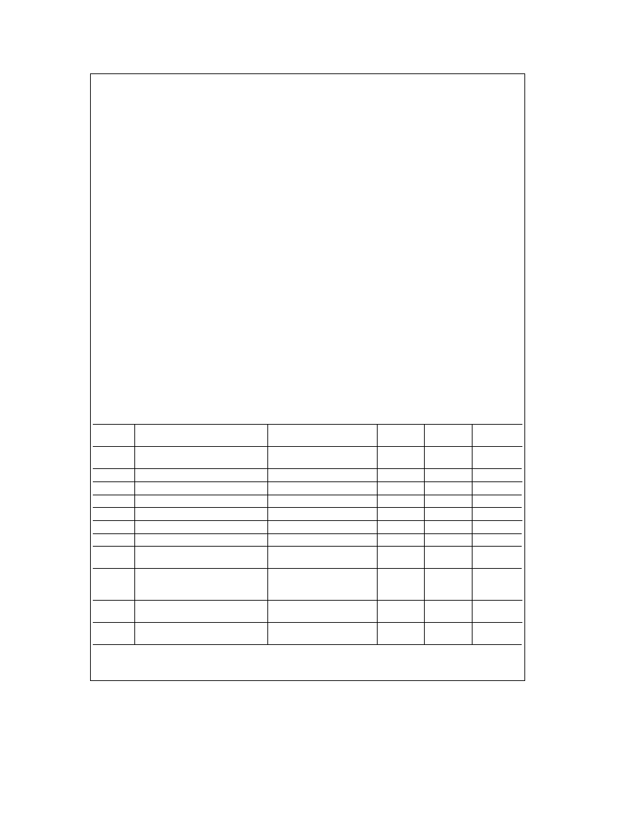
221 Converter Static Characteristics
The following specifications apply to the LM12434 and LM12 L 438 for VAa e
VDa e 5V 33V AGND e DGND e 0V VREFa e 4096V 25V VREFb e 0V 12-bit a sign conversion mode fCLK e
80 MHz
6 MHz
RS e 25X source impedance for VREFa and VREFb s 25X fully-differential input with fixed 2048V
125V common-mode voltage and minimum acquisition time unless otherwise specified Boldface limits apply for TA e
TJ e TMIN to TMAX all other limits TA e TJ e 25 C (Notes 6 7 8 and 9)
Symbol
Parameter
Conditions
Typical
Limits
Units
(Note 10)
(Note 11)
(Limit)
ILE
Positive and Negative Integral
After Auto-Cal (Notes 12 17)
g
035
g
1
LSB (max)
Linearity Error
TUE
Total Unadjusted Error
After Auto-Cal (Note 12)
g
1
LSB
Resolution with No Missing Codes
After Auto-Cal (Note 12)
13
Bits
DNL
Differential Non-Linearity
After Auto-Cal
g
02
g
1
LSB (max)
Zero Error
After Auto-Cal (Notes 13 17)
g
02
g
1
LSB (max)
Positive Full-Scale Error
After Auto-Cal (Notes 12 17)
g
02
g
2
LSB (max)
Negative Full-Scale Error
After Auto-Cal (Notes 12 17)
g
02
g
2
LSB (max)
DC Common Mode Error
(Note 14)
g
2
g
35
LSB (max)
g
40
ILE
8-Bit a Sign and ‘‘Watchdog’’
(Note 12)
Mode Positive and Negative
g
015
g
12
LSB (max)
Integral Linearity Error
TUE
8-Bit a Sign and ‘‘Watchdog’’ Mode
After Auto-Zero
g
12
g
12
LSB (max)
Total Unadjusted Error
8-Bit a Sign and ‘‘Watchdog’’ Mode
9
Bits (max)
Resolution with No Missing Codes
5
相關(guān)PDF資料 |
PDF描述 |
|---|---|
| LM12L438CIWMX | SPECIALTY ANALOG CIRCUIT, PDSO28 |
| LM20323AMHX | 6 A SWITCHING REGULATOR, 570 kHz SWITCHING FREQ-MAX, PDSO20 |
| LM20323AMHE | 6 A SWITCHING REGULATOR, 570 kHz SWITCHING FREQ-MAX, PDSO20 |
| LM20323AMH | 6 A SWITCHING REGULATOR, 570 kHz SWITCHING FREQ-MAX, PDSO20 |
| LM22677QTJ-5.0 | 8.75 A SWITCHING REGULATOR, 600 kHz SWITCHING FREQ-MAX, PSSO7 |
相關(guān)代理商/技術(shù)參數(shù) |
參數(shù)描述 |
|---|---|
| LM12438CIV | 制造商:NSC 制造商全稱:National Semiconductor 功能描述:Sign Data Acquisition System with Serial I/O and Self-Calibration |
| LM12438CIWM | 制造商:NSC 制造商全稱:National Semiconductor 功能描述:Sign Data Acquisition System with Serial I/O and Self-Calibration |
| LM12454 | 制造商:未知廠家 制造商全稱:未知廠家 功能描述:General Purpose Controller Z84C15 |
| LM12454_06 | 制造商:NSC 制造商全稱:National Semiconductor 功能描述:12-Bit + Sign Data Acquisition System with Self-Calibration |
| LM12454A WAF | 制造商:Texas Instruments 功能描述: |
發(fā)布緊急采購(gòu),3分鐘左右您將得到回復(fù)。