- 您現(xiàn)在的位置:買賣IC網(wǎng) > PDF目錄383237 > L6563 (意法半導體) ADVANCED TRANSITION-MODE PFC CONTROLLER PDF資料下載
參數(shù)資料
| 型號: | L6563 |
| 廠商: | 意法半導體 |
| 元件分類: | 基準電壓源/電流源 |
| 英文描述: | ADVANCED TRANSITION-MODE PFC CONTROLLER |
| 中文描述: | 先進的轉(zhuǎn)型模式PFC控制器 |
| 文件頁數(shù): | 13/25頁 |
| 文件大小: | 362K |
| 代理商: | L6563 |
13/25
L6563
4.2 Feedback failure protection (FFP)
The OVP function above described is able to handle "normal" overvoltage conditions, i.e. those resulting
from an abrupt load/line change or occurring at start-up. It cannot handle the overvoltage generated, for
instance, when the upper resistor of the output divider (R1) fails open: the voltage loop can no longer read
the information on the output voltage and will force the PFC pre-regulator to work at maximum ON-time,
causing the output voltage to rise with no control.
A pin of the device (PFC_OK) has been dedicated to provide an additional monitoring of the output voltage
with a separate resistor divider (R3 high, R4 low, see
Figure 35
). This divider is selected so that the voltage
at the pin reaches 2.5V if the output voltage exceeds a preset value, usually larger than the maximum Vo
that can be expected, also including worst-case load/line transients.
Example: Vo = 400 V, Vox = 475 V. Select: R3=3M
; then: R4=3M
·2.5/(475-2.5)=15.87k
.
When this function is triggered, the gate drive activity is immediately stopped, the device is shut down, its
quiescent consumption is reduced below 250 μA and the condition is latched as long as the supply voltage
of the IC is above the UVLO threshold. At the same time the pin PWM_LATCH is asserted high.
PWM_LATCH is an open source output able to deliver 3.7V min. with 0.5 mA load, intended for tripping a
latched shutdown function of the PWM controller IC in the cascaded DC-DC converter, so that the entire
unit is latched off. To restart the system it is necessary to recycle the input power, so that the Vcc voltages
of both the L6563 and the PWM controller go below their respective UVLO thresholds.
The PFC_OK pin doubles its function as a not-latched IC disable: a voltage below 0.2V will shut down the
IC, reducing its consumption below 1 mA. In this case both PWM_STOP and PWM_LATCH keep their
high impedance status. To restart the IC simply let the voltage at the pin go above 0.26 V.
Note that this function offers a complete protection against not only feedback loop failures or erroneous
settings, but also against a failure of the protection itself. Either resistor of the PFC_OK divider failing short
or open or a PFC_OK pin floating will result in shutting down the IC and stopping the pre-regulator.
4.3 Voltage Feedforward
The power stage gain of PFC pre-regulators varies with the square of the RMS input voltage. So does the
crossover frequency f
c
of the overall open-loop gain because the gain has a single pole characteristic. This
leads to large trade-offs in the design.
For example, setting the gain of the error amplifier to get f
c
= 20 Hz @ 264 Vac means having f
c
4 Hz @
88 Vac, resulting in a sluggish control dynamics. Additionally, the slow control loop causes large transient
current flow during rapid line or load changes that are limited by the dynamics of the multiplier output. This
limit is considered when selecting the sense resistor to let the full load power pass under minimum line
voltage conditions, with some margin. But a fixed current limit allows excessive power input at high line,
whereas a fixed power limit requires the current limit to vary inversely with the line voltage.
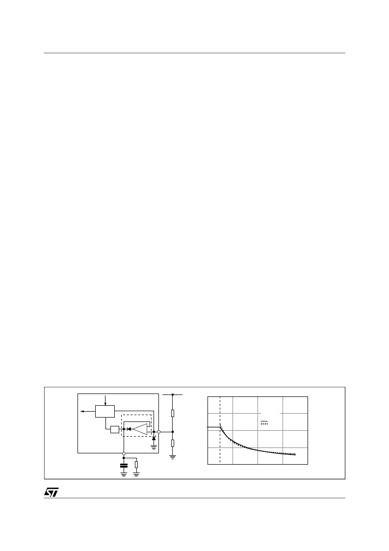
Voltage Feedforward can compensate for the gain variation with the line voltage and allow overcoming all
of the above-mentioned issues. It consists of deriving a voltage proportional to the input RMS voltage,
feeding this voltage into a squarer/divider circuit (1/V
2
corrector) and providing the resulting signal to the
multiplier that generates the current reference for the inner current control loop (see
Figure 36
).
Figure 36. Voltage feedforward: squarer-divider (1/V
2
) block diagram and transfer characteristic
0
1
2
3
4
0
0.5
1
1.5
2
V
FF
=V
MULT
Vcsx
0.5
V
COMP
=4V
Actual
Ideal
5
MULT
3
R5
Rectified mains
R6
"ideal" diode
rcurrent
(Vcsx)
9.5V
VFF
C
FF
R
FF
(V
COMP
)
-
+
1/V
2
MULTIPLIER
L6563
相關PDF資料 |
PDF描述 |
|---|---|
| L6563TR | ADVANCED TRANSITION-MODE PFC CONTROLLER |
| L6566A | Multi-mode controller for SMPS with PFC front-end |
| L6566ATR | Multi-mode controller for SMPS with PFC front-end |
| L6566B | Multi-mode controller for SMPS |
| L6566BTR | Multi-mode controller for SMPS |
相關代理商/技術參數(shù) |
參數(shù)描述 |
|---|---|
| L6563_07 | 制造商:STMICROELECTRONICS 制造商全稱:STMicroelectronics 功能描述:Advanced transition-mode PFC controller |
| L6563A | 功能描述:功率因數(shù)校正 IC Advanced transition mode PFC controller RoHS:否 制造商:Fairchild Semiconductor 開關頻率:300 KHz 最大功率耗散: 最大工作溫度:+ 125 C 安裝風格:SMD/SMT 封裝 / 箱體:SOIC-8 封裝:Reel |
| L6563ATR | 功能描述:功率因數(shù)校正 IC Advanced transition mode PFC controller RoHS:否 制造商:Fairchild Semiconductor 開關頻率:300 KHz 最大功率耗散: 最大工作溫度:+ 125 C 安裝風格:SMD/SMT 封裝 / 箱體:SOIC-8 封裝:Reel |
| L6563CYTR | 制造商:ST 功能描述:ADVANCED TRANSITION-MODE PFC CONTROLLER |
| L6563H | 功能描述:功率因數(shù)校正 IC High voltage start Transition-mode PFC RoHS:否 制造商:Fairchild Semiconductor 開關頻率:300 KHz 最大功率耗散: 最大工作溫度:+ 125 C 安裝風格:SMD/SMT 封裝 / 箱體:SOIC-8 封裝:Reel |
發(fā)布緊急采購,3分鐘左右您將得到回復。