- 您現(xiàn)在的位置:買賣IC網(wǎng) > PDF目錄377510 > IRFP4232PBF (International Rectifier) PDP MOSFET PDF資料下載
參數(shù)資料
| 型號: | IRFP4232PBF |
| 廠商: | International Rectifier |
| 英文描述: | PDP MOSFET |
| 中文描述: | MOSFET的等離子 |
| 文件頁數(shù): | 2/8頁 |
| 文件大小: | 293K |
| 代理商: | IRFP4232PBF |

2
www.irf.com
S
D
G
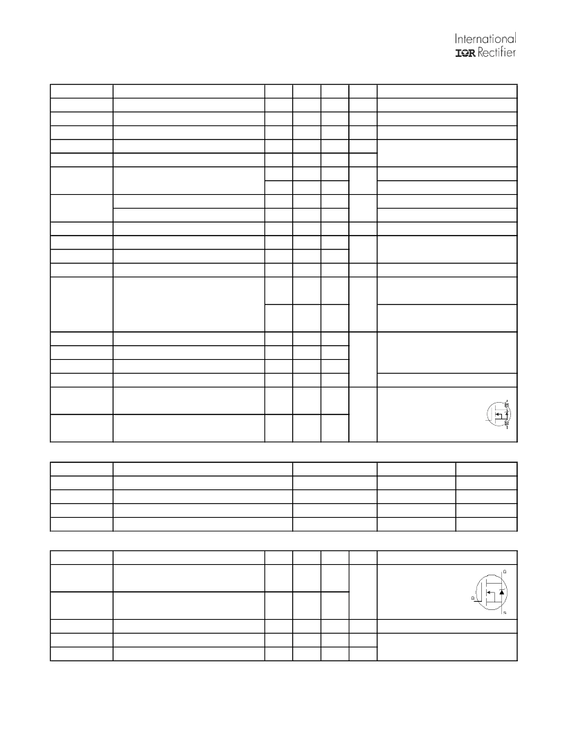
Electrical Characteristics @ T
J
= 25°C (unless otherwise specified)
Parameter
BV
DSS
Drain-to-Source Breakdown Voltage
Β
V
DSS
/
T
J
Breakdown Voltage Temp. Coefficient
R
DS(on)
Static Drain-to-Source On-Resistance
V
GS(th)
Gate Threshold Voltage
V
GS(th)
/
T
J
Gate Threshold Voltage Coefficient
I
DSS
Drain-to-Source Leakage Current
Min.
250
Typ.
–––
Max. Units
–––
V
–––
180
–––
mV/°C
m
V
–––
30
35.7
3.0
–––
5.0
–––
-15
–––
mV/°C
–––
–––
5.0
μA
–––
–––
150
I
GSS
Gate-to-Source Forward Leakage
–––
–––
100
nA
Gate-to-Source Reverse Leakage
–––
–––
-100
g
fs
Q
g
Q
gd
t
st
Forward Transconductance
95
–––
–––
S
Total Gate Charge
–––
160
240
nC
Gate-to-Drain Charge
–––
60
–––
Shoot Through Blocking Time
100
–––
–––
ns
E
PULSE
Energy per Pulse
μJ
C
iss
C
oss
C
rss
C
oss
eff.
L
D
Input Capacitance
–––
7290
–––
Output Capacitance
–––
610
–––
pF
Reverse Transfer Capacitance
–––
240
–––
Effective Output Capacitance
–––
420
–––
Internal Drain Inductance
–––
5.0
–––
Between lead,
nH
6mm (0.25in.)
L
S
Internal Source Inductance
–––
13
–––
from package
and center of die contact
Avalanche Characteristics
Parameter
Units
E
AS
E
AR
V
DS(Avalanche)
I
AS
Single Pulse Avalanche Energy
mJ
Repetitive Avalanche Energy
mJ
Repetitive Avalanche Voltage
V
Avalanche Current
A
Diode Characteristics
Parameter
Min.
–––
Typ.
–––
Max. Units
60
I
S
@ T
C
= 25°C Continuous Source Current
(Body Diode)
I
SM
Pulsed Source Current
(Body Diode)
V
SD
Diode Forward Voltage
t
rr
Reverse Recovery Time
Q
rr
Reverse Recovery Charge
A
–––
–––
240
–––
–––
1.0
V
–––
240
360
ns
–––
1230
1850
nC
MOSFET symbol
V
DS
= 25V, I
D
= 42A
V
DD
= 125V, I
D
= 42A, V
GS
= 10V
Conditions
V
DD
= 200V, V
GS
= 15V, R
G
= 4.7
L = 220nH, C= 0.4μF, V
GS
= 15V
V
DS
= 200V, R
G
= 4.7
,
T
J
= 25°C
L = 220nH, C= 0.4μF, V
GS
= 15V
V
DS
= 200V, R
G
= 4.7
,
T
J
= 100°C
V
GS
= 0V
V
DS
= 25V
= 1.0MHz, See Fig.9
V
DS
= V
GS
, I
D
= 250μA
V
DS
= 200V, V
GS
= 0V
V
DS
= 200V, V
GS
= 0V, T
J
= 125°C
V
GS
= 20V
V
GS
= -20V
V
GS
= 0V, V
DS
= 0V to 200V
Conditions
V
GS
= 0V, I
D
= 250μA
Reference to 25°C, I
D
= 1mA
V
GS
= 10V, I
D
= 42A
T
J
= 25°C, I
F
= 42A, V
DD
= 50V
di/dt = 100A/μs
T
J
= 25°C, I
S
= 42A, V
GS
= 0V
showing the
integral reverse
p-n junction diode.
Typ.
Max.
–––
220
43
42
–––
–––
300
–––
–––
310
–––
–––
950
–––
相關(guān)PDF資料 |
PDF描述 |
|---|---|
| IRFP4242PBF | PDP MOSFET |
| IRFP440 | Power MOSFET(Vdss=500V, Rds(on)=0.85ohm, Id=8.8A) |
| IRFP450N | Power MOSFET(Vdss=500V, Rds(on)max=0.37ohm, Id=14A) |
| IRFP450 | Power MOSFET(Vdss=500V, Rds(on)=0.40ohm, Id=14A) |
| IRFP450 | N-CHANNEL POWER MOSFETS |
相關(guān)代理商/技術(shù)參數(shù) |
參數(shù)描述 |
|---|---|
| IRFP4232PBF | 制造商:International Rectifier 功能描述:MOSFET |
| IRFP4232PBF_07 | 制造商:IRF 制造商全稱:International Rectifier 功能描述:Advanced process technology |
| IRFP4242PBF | 功能描述:MOSFET PDP SWITCH 300V 1 N-CH HEXFET RoHS:否 制造商:STMicroelectronics 晶體管極性:N-Channel 汲極/源極擊穿電壓:650 V 閘/源擊穿電壓:25 V 漏極連續(xù)電流:130 A 電阻汲極/源極 RDS(導通):0.014 Ohms 配置:Single 最大工作溫度: 安裝風格:Through Hole 封裝 / 箱體:Max247 封裝:Tube |
| IRFP430 | 制造商:未知廠家 制造商全稱:未知廠家 功能描述:TRANSISTOR | MOSFET | N-CHANNEL | 500V V(BR)DSS | 4.5A I(D) | TO-247VAR |
| IRFP431 | 制造商:未知廠家 制造商全稱:未知廠家 功能描述:TRANSISTOR | MOSFET | N-CHANNEL | 450V V(BR)DSS | 4.5A I(D) | TO-247VAR |
發(fā)布緊急采購,3分鐘左右您將得到回復。