- 您現(xiàn)在的位置:買賣IC網(wǎng) > PDF目錄360867 > INTEL387DX Intel387 DX - MATH COPROCESSOR PDF資料下載
參數(shù)資料
| 型號(hào): | INTEL387DX |
| 英文描述: | Intel387 DX - MATH COPROCESSOR |
| 中文描述: | Intel387霉素-數(shù)學(xué)協(xié)處理器 |
| 文件頁(yè)數(shù): | 27/41頁(yè) |
| 文件大?。?/td> | 435K |
| 代理商: | INTEL387DX |
第1頁(yè)第2頁(yè)第3頁(yè)第4頁(yè)第5頁(yè)第6頁(yè)第7頁(yè)第8頁(yè)第9頁(yè)第10頁(yè)第11頁(yè)第12頁(yè)第13頁(yè)第14頁(yè)第15頁(yè)第16頁(yè)第17頁(yè)第18頁(yè)第19頁(yè)第20頁(yè)第21頁(yè)第22頁(yè)第23頁(yè)第24頁(yè)第25頁(yè)第26頁(yè)當(dāng)前第27頁(yè)第28頁(yè)第29頁(yè)第30頁(yè)第31頁(yè)第32頁(yè)第33頁(yè)第34頁(yè)第35頁(yè)第36頁(yè)第37頁(yè)第38頁(yè)第39頁(yè)第40頁(yè)第41頁(yè)

Intel387
TM
DX MATH COPROCESSOR
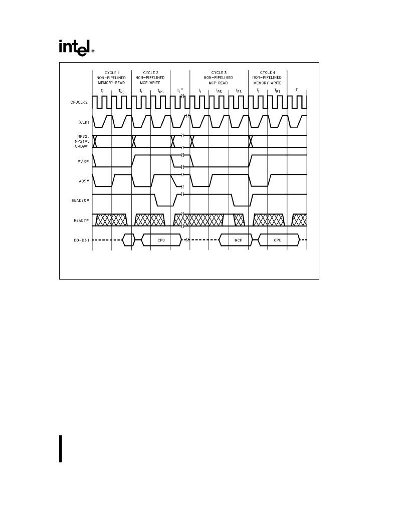
240448–10
Cycles 1 & 2 represent part of the operand transfer cycle for instructions involving either 4-byte or 8-byte operand loads.
Cycles 3 & 4 represent part of the operand transfer cycle for a store operation.
*
Cycles 1 & 2 could repeat here or T
I
states for various non-operand transfer cycles and overhead.
Figure 3.5. Nonpipelined Read and Write Cycles
3.4.2 PIPELINED BUS CYCLES
Because all the activities of the Intel387 DX MCP
bus interface occur either during the T
RS
state or
during the transitions to or from that state, the only
difference between a pipelined and a nonpipelined
cycle is the manner of changing from one state to
another. The exact activities in each state are de-
tailed in the previous section ‘‘Nonpipelined Bus Cy-
cles’’.
When the Intel386 DX CPU asserts ADS
Y
before
the end of a bus cycle, both ADS
Y
and READY
Y
are active during a T
RS
state. This condition causes
the MCP to change to a different state named T
P
.
The MCP activities in the transition from a T
RS
state
to a T
P
state are exactly the same as those in the
transition from a T
RS
state to a T
I
state in nonpipe-
lined cycles.
T
P
state is metastable; therefore, one clock period
later the MCP returns to T
RS
state. In consecutive
pipelined cycles, the MCP bus logic uses only T
RS
and T
P
states.
Figure 3.6 shows the fastest transition into and out
of the pipelined bus cycles. Cycle 1 in this figure
represents a nonpipelined cycle. (Nonpipelined write
cycles with only one T
RS
state (i.e. no wait states)
are always followed by another nonpipelined cycle,
because READY
Y
is asserted before the earliest
possible assertion of ADS
Y
for the next cycle.)
Figure 3.7 shows the pipelined write and read cycles
with one additional T
RS
states beyond the minimum
required. To delay the assertion of READY
Y
re-
quires external logic.
27
27
相關(guān)PDF資料 |
PDF描述 |
|---|---|
| INTEL740 | 64-Bit Graphics (GUI) Accelerator |
| INTRO_TO_TRANSISTOR | |
| INTRUMENT | For EM60000 series |
| IO100VXI | |
| IO110VXI | |
相關(guān)代理商/技術(shù)參數(shù) |
參數(shù)描述 |
|---|---|
| INTEL387SX | 制造商:INTEL 制造商全稱:Intel Corporation 功能描述:Intel387 SX - MATH COPROCESSOR |
| INTEL387TMDX | 制造商:INTEL 制造商全稱:Intel Corporation 功能描述:Intel387TM DX MATH COPROCESSOR |
| INTEL740 | 制造商:未知廠家 制造商全稱:未知廠家 功能描述:64-Bit Graphics (GUI) Accelerator |
| INTEL82801 | 制造商:INTEL 制造商全稱:Intel Corporation 功能描述:82801AB (ICH0) I/O Controller Hub |
| INTEL82802AB | 制造商:INTEL 制造商全稱:Intel Corporation 功能描述:Firmware Hub (FWH) |
發(fā)布緊急采購(gòu),3分鐘左右您將得到回復(fù)。