- 您現(xiàn)在的位置:買賣IC網(wǎng) > PDF目錄371898 > HSP50016JC-52 (INTERSIL CORP) Digital Down Converter PDF資料下載
參數(shù)資料
| 型號: | HSP50016JC-52 |
| 廠商: | INTERSIL CORP |
| 元件分類: | 數(shù)字信號處理外設(shè) |
| 英文描述: | Digital Down Converter |
| 中文描述: | 16-BIT, DSP-MIXER, PQCC44 |
| 封裝: | PLASTIC, LCC-44 |
| 文件頁數(shù): | 22/31頁 |
| 文件大?。?/td> | 209K |
| 代理商: | HSP50016JC-52 |
第1頁第2頁第3頁第4頁第5頁第6頁第7頁第8頁第9頁第10頁第11頁第12頁第13頁第14頁第15頁第16頁第17頁第18頁第19頁第20頁第21頁當(dāng)前第22頁第23頁第24頁第25頁第26頁第27頁第28頁第29頁第30頁第31頁

3-219
An example of the control word contents for this mode of
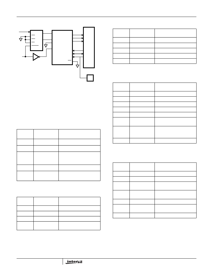
operation is given in Tables 11 through 17. In this setup, the
DDC has been configured for a constant down conversion
frequency, decimation by 64 and Test Features disabled. Bit
fields of three bits or less are in binary notation; longer fields
are in hexadecimal. Control Words Zero and Seven are not
used.
TABLE 11. SAMPLE FORMAT FOR CONTROL WORD 1 -
PHASE GENERATOR/TEST ENABLE
BIT
POSITION
FUNCTION
DESCRIPTION
39-37
Address
001 = Control Word 1.
36
Update
1 = Control Register Update.
35-4
Minimum Phase
Increment
Minimum Phase Increment
Computed according to
[f
C
/f
S
] 2
33.
3
Test Enable
0 = Test Features Disabled.
2-0
Phase Generator
Mode
001 = Normal Mode.
0011 XXXX XXXX XXXX XXXX XXXX XXXX XXXX XXXX 0001
TABLE 12. SAMPLE FORMAT FOR CONTROL WORD 2 -
PHASE GENERATOR
BIT
POSITION
FUNCTION
DESCRIPTION
39-37
Address
010 = Control Word 2.
36
Update
1 = Control Register Update.
35-32
Reserved
All Zeroes.
31-0
Maximum Phase
Increment
All Zeroes.
0101 0000 0000 0000 0000 0000 0000 0000 0000 0000
MICROPROCESSOR
.
5MHz
V
IN
CS
OE
A0
CONV
D.
D0
OSCILLATOR
DR
CLKR
FSR
DX
CLKX
FSX
12-BIT
ADC
HSP50016
I
IQCLK
IQSTB
CDATA
CCLK
CSTB
CS
DA.
DATA4
DATA0-3
CLK
FIGURE 16. CIRCUIT FOR SINGLE CHANNEL OPERATION
TABLE 13. SAMPLE FORMAT FOR CONTROL WORD 3 -
PHASE GENERATOR/OUTPUT TIME SLOT
BIT
POSITION
FUNCTION
DESCRIPTION
39-37
Address
011 = Control Word 3.
36
Update
1 = Control Register Update.
35-32
Reserved
All Zeroes.
31-18
Time Slot Length
All Zeroes.
17-0
Phase Offset
All Zeroes.
0111 0000 0000 0000 0000 0000 0000 0000 0000 0000
TABLE 14. SAMPLE FORMAT FOR CONTROL WORD 4 -
PHASE GENERATOR/HDF/OUTPUT
BIT
POSITION
FUNCTION
DESCRIPTION
39-37
Address
100 = Control Word 4.
36
Update
1 = Control Register Update.
35-33
Reserved
All Zeroes.
32
Up Convert
0 = Do Not Up convert.
31
Real Mode
0 = Complex Mode.
30-7
Delta Phase
Increment
All Zeroes.
6-1
Shift
37 = Decimal 55, the Shift
Corresponding to HDF
Decimation by 16.
0
Spectral Reverse
0 = No Spectral Reversal
1001 0000 0000 0000 0000 0000 0000 0000 0110 1110
TABLE 15. SAMPLE FORMAT FOR CONTROL WORD 5
HDF/OUTPUT
BIT
POSITION
FUNCTION
DESCRIPTION
39-37
Address
101 = Control Word 5.
36
Update
1 = Control Register Update.
35-21
HDF Decimation
Counter Preload
F = Decimation by 16 in HDF.
20-5
Scaling Multiplier
Gain
8000 = Scaling Multiplier
Gain of 1.
4-3
Output Format
00 = Two’s Complement.
2-1
Number of Output
Bits
00 = 16-Bits.
0
Output Sense
1 = MSB First.
1011 0000 0000 0001 1111 0000 0000 0000 0000 0000
HSP50016
相關(guān)PDF資料 |
PDF描述 |
|---|---|
| HSP50016JC-75 | Digital Down Converter |
| HSP50110JC-60 | Communications Tuner Circuit |
| HSP50306SC-25 | Digital QPSK Demodulator |
| HSP50306SC-2596 | Digital QPSK Demodulator |
| HSP50306SC-27 | Digital QPSK Demodulator |
相關(guān)代理商/技術(shù)參數(shù) |
參數(shù)描述 |
|---|---|
| HSP50016JC-5296 | 制造商:Rochester Electronics LLC 功能描述:TAPE AND REEL OF HSP50016JC-52 - Bulk |
| HSP50016JC-75 | 制造商:Rochester Electronics LLC 功能描述:DIGITAL DOWN CONVERTER 44 PLCC 75MHZ COMM - Bulk |
| HSP50016JI-52 | 制造商:Rochester Electronics LLC 功能描述:DIGITAL DOWN CONVERTER 44 PLCC, 52MHZ, COMM,INDS - Bulk |
| HSP50016JM-5296R3571 | 制造商:Intersil Corporation 功能描述:ROCKWELL HSP50016JC-5296 W/BRAND,-55/+125C OP TEMP,ELECTR - Tape and Reel |
| HSP50016JM-52R3571 | 制造商:Rochester Electronics LLC 功能描述:- Bulk |
發(fā)布緊急采購,3分鐘左右您將得到回復(fù)。