- 您現(xiàn)在的位置:買賣IC網(wǎng) > PDF目錄370474 > HD74AC (Hitachi,Ltd.) HD74AC Series Common Information PDF資料下載
參數(shù)資料
| 型號: | HD74AC |
| 廠商: | Hitachi,Ltd. |
| 英文描述: | HD74AC Series Common Information |
| 中文描述: | HD74AC系列通用信息 |
| 文件頁數(shù): | 48/52頁 |
| 文件大?。?/td> | 220K |
| 代理商: | HD74AC |
第1頁第2頁第3頁第4頁第5頁第6頁第7頁第8頁第9頁第10頁第11頁第12頁第13頁第14頁第15頁第16頁第17頁第18頁第19頁第20頁第21頁第22頁第23頁第24頁第25頁第26頁第27頁第28頁第29頁第30頁第31頁第32頁第33頁第34頁第35頁第36頁第37頁第38頁第39頁第40頁第41頁第42頁第43頁第44頁第45頁第46頁第47頁當前第48頁第49頁第50頁第51頁第52頁

Design Considerations
47
1.000
0.000
0.000
5.000
0.5000V/dlc
V
IN
I
C
0
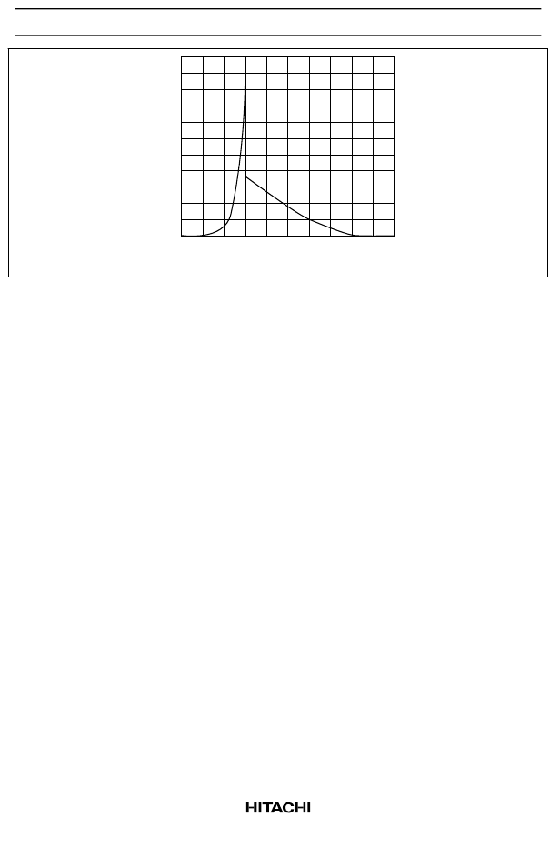
Figure 21 I
CC
versus Input Voltage for HD74ACT Devices
The Delta I
CC
specification is the increase in I
CC
. For each input at V
CC
-2.1 V, the Delta I
CC
value should be
added to the quiescent supply current to arrive at the circuit’s worst-case static I
CC
value.
Fortunately, there are several factors which tend to reduce the increase in I
CC
per input. Most TTL devices
will be able to drive FACT inputs well beyond the TTL output specification due to FACT’s low input
loading in a typical system. For example, FAST logic outputs can drive HD74ACT-type inputs down to
200 mV and up to 3.5 V. Additionally, the typical I
CC
increase per input will be less than the specified
limit. As shown in the graph above, the I
CC
increase at V
CC
-2.1 V is less than 200
μ
A in the typical system.
Experiments have shown that the I
CC
of an HD74ACT240 series device typically increases only 200
μ
A
when all of the inputs are connected to a FAST device instead of ground or V
CC
.
It is important when designing with FACT, as with any TTL-compatible CMOS technology, that the Delta
I
CC
specification be considered. Designers should be aware of the spec’s significance and that the data
book specification is a worst-case value; most systems will see values that are much less.
7. Testing Advanced CMOS Devices with I/O Pins
There are more and more CMOS families becoming available which can replace TTL circuits. Although
testing these new CMOS units with programs and fixtures which were developed for bipolar devices will
yield acceptable results most of the time, there are some cases where this approach will cause the test
engineer problems.
Such is the case with parts that have a bidirectional pin, exemplified by the HD74AC245/HD74ACT245
octal transceiver. If the proper testing methods are not followed, these types of parts may not pass those
tests for I
CC
and input leakage currents, even when there is no fault with the devices.
CMOS circuits, unlike their bipolar counterparts, have static I
CC
specification orders of magnitude less than
standard load currents. Most CMOS I
CC
specifications are usually less than 100
μ
A. When conducting an
I
CC
test, greater care must be taken so that other currents will not mask the actual I
CC
so that other currents
will not mask the actual I
CC
of the device. These currents are usually sourced from the inputs and outputs.
相關(guān)PDF資料 |
PDF描述 |
|---|---|
| HD74ALVC162244 | 16-bit Buffer / Driver with 3-state Outputs(帶三態(tài)輸出的16位緩沖器/驅(qū)動器) |
| HD74ALVC162334 | 16-bit Universal Bus Driver with 3-state Outputs(帶三態(tài)輸出的16位通用總線驅(qū)動器) |
| HD74ALVC16244 | 16-bit Buffer / Driver with 3-state Outputs(帶三態(tài)輸出的16位緩沖器/驅(qū)動器) |
| HD74ALVC162831 | 1-bit to 4-bit Address Register / Driver with 3-state Outputs(三態(tài)輸出的1位-4位地址寄存器/驅(qū)動器) |
| HD74ALVC162834A | 1-Of-8 Data Selectors/Multiplexers 16-CDIP -55 to 125 |
相關(guān)代理商/技術(shù)參數(shù) |
參數(shù)描述 |
|---|---|
| HD74AC00 | 制造商:HITACHI 制造商全稱:Hitachi Semiconductor 功能描述:Quad 2-Input NAND Gate |
| HD74AC00FP | 制造商:未知廠家 制造商全稱:未知廠家 功能描述:Quad 2-input NAND Gate |
| HD74AC00FPEL | 制造商:RENESAS 制造商全稱:Renesas Technology Corp 功能描述:Quad 2-Input NAND Gate |
| HD74AC00P | 制造商:RENESAS 制造商全稱:Renesas Technology Corp 功能描述:Quad 2-Input NAND Gate |
| HD74AC00RPEL | 制造商:RENESAS 制造商全稱:Renesas Technology Corp 功能描述:Quad 2-Input NAND Gate |
發(fā)布緊急采購,3分鐘左右您將得到回復(fù)。