- 您現(xiàn)在的位置:買賣IC網(wǎng) > PDF目錄370216 > FPD03784 PDF資料下載
參數(shù)資料
| 型號: | FPD03784 |
| 元件分類: | 顯示驅(qū)動器 |
| 文件頁數(shù): | 3/12頁 |
| 文件大小: | 199K |
| 代理商: | FPD03784 |

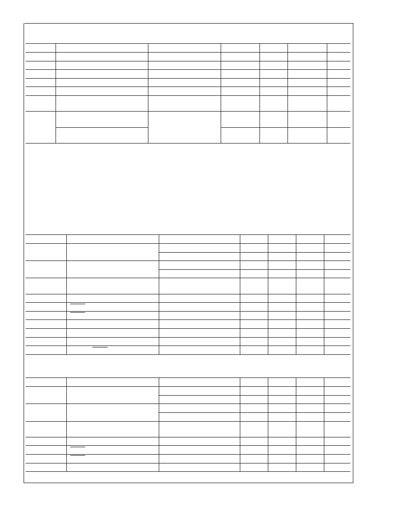
Analog Electrical Characteristics
(Continued)
Symbol
A
IHBIAS
R
CSTIME
C
CSTIME
I
SIN
I
REF
R
DAC
Parameter
Conditions
Min
Typ
22.5
12
100
40
Max
Units
I
SIN
to I
HBIAS
Gain Factor
CSTIME resistance
CSTIME capacitance
Input Current Source
Amplifier Reference Current
RDAC References (V
GMA1
to
V
GMA6
and V
GMA7
to V
GMA12
)
Output Peak to Peak Error (gray
levels 0 through 58)
Output Peak to Peak Error (gray
levels 59 through 63)
5
k
pF
μA
μA
150
100
75
16
10
each
12.0
15.0
18.0
k
V
pperr
V
GMA1
= V
DD2
0.2V
V
GMA12
= V
SS2
+ 0.2V
(Note 8)
±
3
±
12
mV
±
5
±
25
mV
Note 5:
V
= 9.5V, V
= 9.5V, R
= 220 k
, R
ISIN
= 470 k
, V
= 3.3V, DCLK = 65 MHz, R
LOAD
= 5 k
, C
LOAD
= 50 pF, charge share time = 1.5
μs, all other swinging between V
GMA1
(= 8.0V) and V
GMA12
(= 0.5V) with a line time = 22 μs.
Note 6:
The following relationship must be maintained between the reference voltages: V
DD2
>
V
GMA1
>
V
GMA2
>
V
GMA3
>
V
GMA4
>
V
GMA5
>
V
GMA6
>
V
GMA7
>
V
GMA8
>
V
GMA9
>
V
GMA10
>
V
GMA11
>
V
GMA12
>
V
SS2
Note 7:
I
is the current delivered into a potential of 0.2V when the output is commanded to a potential of V
DD2
0.2V or the current into the output from a
potential of V
DD2
0.2V when the output is commanded to 0.2V (V
SS2
= 0V).
Note 8:
This parameter reflects the error in peak-to-peak output voltage for each gray-level when the output swings from the gray-level high value, VHxx, to its low
value, VLxx. This parameter applies to every output on the die. The
Typical
value represents one standard deviation from ideal based on tester data. The
Maximum
value is a constraint of the test environment, not the performance of the part.
Note 9:
Current into device pins is defined as positive. Current out of device pins is defined as negative.
AC Electrical Characteristics
Digital AC Characteristics (3.3V Logic)
Symbol
CLK
Parameter
Conditions
Min
Typ
Max
65.0
27.5
Units
MHz
MHz
ns
ns
Data Clock Frequency
SINGLE = 1 (Note 10)
SINGLE = 0 (Note 10)
SINGLE = 1 (Note 10)
SINGLE = 0 (Note 10)
t
WDCP
CLK Clock Pulse Width
5
10
t
DSU
Data Setup DX[5:0], POL,
INVTxxx
Data Hold DX[5:0], POL, INVTxxx
LOAD Pulse Width
LOAD to First ENIO Setup
ENIOx Input to CLK Setup
ENIOx Input Pulse Width
ENIOx Output Prop Delay
Delay to LOAD Pulse
4
ns
t
DHLD
t
TWP
t
LDENSU
t
ENDCSU
t
WEN
t
ENPR
t
LDLY
4
50
200
2.5
10
ns
ns
ns
ns
ns
ns
(Note 11)
Load = 20pF
12
3
CLKs
Digital AC Characteristics (2.5V Logic)
Symbol
CLK
Parameter
Conditions
Min
Typ
Max
40.0
17.5
Units
MHz
MHz
ns
ns
Data Clock Frequency
SINGLE = 1 (Note 10)
SINGLE = 0 (Note 10)
SINGLE = 1 (Note 10)
SINGLE = 0(Note 10)
t
WDCP
CLK Clock Pulse Width
10
25
t
DSU
Data Setup DX[5:0], POL,
INVTxxx
Data Hold DX[5:0], POL, INVTxxx
LOAD Pulse Width
LOAD to First ENIO Setup
ENIOx Input to CLK Setup
4
ns
t
DHLD
t
TWP
t
LDENSU
t
ENDCSU
6
50
200
4
ns
ns
ns
ns
(Note 11)
F
www.national.com
3
相關(guān)PDF資料 |
PDF描述 |
|---|---|
| FPD10000AF | 10W PACKAGED POWER PHEMT |
| FPD10000V | 10W POWER PHEMT FOR WIMAX POWER AMPLIFIERS |
| FPD1000AS | 1W PACKAGED POWER PHEMT |
| FPD1000V | CAP,SMD,TANT,22UF,20%,6.3V,A |
| FPD1050 | 0.75W POWER PHEMT |
相關(guān)代理商/技術(shù)參數(shù) |
參數(shù)描述 |
|---|---|
| FPD06SCC200 | 制造商:Carlo Gavazzi 功能描述:FIBRE PL STD 1MM DR 200CM |
| FPD07SCS200 | 制造商:Carlo Gavazzi 功能描述:FIBRE PL STD 1MM DR 200CM |
| FPD08SCM200 | 制造商:Carlo Gavazzi 功能描述:FIBRE PL STD 1MM DR 200CM |
| FPD08SCS200 | 制造商:Carlo Gavazzi 功能描述:FIBRE PL STD 1MM DR 200CM |
| FPD09SAS200 | 制造商:Carlo Gavazzi 功能描述:FIBRE PL STD 0.25MM DR 200CM |
發(fā)布緊急采購,3分鐘左右您將得到回復(fù)。