- 您現(xiàn)在的位置:買賣IC網(wǎng) > PDF目錄370213 > FMS9875KGC140 Integrated Photo Flash Charger and IGBT Driver 16-QFN -35 to 85 PDF資料下載
參數(shù)資料
| 型號(hào): | FMS9875KGC140 |
| 英文描述: | Integrated Photo Flash Charger and IGBT Driver 16-QFN -35 to 85 |
| 文件頁數(shù): | 17/29頁 |
| 文件大小: | 481K |
| 代理商: | FMS9875KGC140 |
第1頁第2頁第3頁第4頁第5頁第6頁第7頁第8頁第9頁第10頁第11頁第12頁第13頁第14頁第15頁第16頁當(dāng)前第17頁第18頁第19頁第20頁第21頁第22頁第23頁第24頁第25頁第26頁第27頁第28頁第29頁

FMS9875
PRODUCT SPECIFICATION
REV. 1.2.15 1/14/02
17
Values of IPUMP and FVCO are set through the PLL
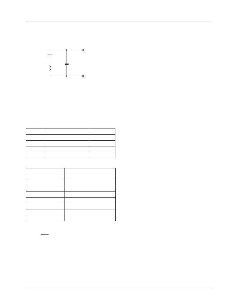
Configuration Register (0x0C). Recommended external filter
components are shown in Figure 16. RF quality ±10%
ceramic capacitors with X7R dielectric are recommended.
Figure 16. Schematic, PLL Filter.
Loop performance is established by setting:
1.
VCO frequency range through FVCO
1-0
. (see Table 8)
Charge Pump Current through IPUMP
2-0
. (see Table 9)
External loop filter component values.
2.
3.
Setting PHASE
4-0
selects the sampling phase of SCK rela-
tive to PXCK in 32 steps of 11.25°. Phase of the output data,
DCK and DCK is slaved to the SCK phase.
RMS Clock jitter is less than 2% of pixel period in all operat-
ing modes.
At frequencies below 80 MHz, the percentage jitter begins to
rise. Increased jitter at low frequencies can be counteracted
in either of two ways:
1.
Use 2X over-sampling. For example with NTSC-601,
the 1X sample rate should be 13.5 MHz. If the divide
ratio is increased from 858 (PLLN = 857) to 1716
(PLLN = 1715), the sampling rate is 27 MHz.
2.
Use 1X sampling by doubling the VCO frequency, then
dividing the PLL frequency by two. For example, with
NTSC-601, the divide ratio is doubled to 1716
(PLLN = 1715), then the sub-divide ratio is set to two
(SUBDIV
1-0
= 01) to reduce the sampling rate from
27 MHz to 13.5 MHz with 858 pixels per line.
COAST
When COAST is active, PLL lock to HSIN is disabled, while
the VCO frequency is retained. VCO frequency remains
stable over several lines without updates from HSIN.
COAST can be connected directly to the vertical sync signal
or supplied by the graphics controller. If 1/2H pulses are
present within HSIN, the COAST period must encompass all
1/2H pulses. COAST polarity may be inverted using the
COASTPOL register bit. In the description below, the setting
COASTPOL = H is used.
Operation of COAST is depicted in Figure 17. HSOUT
polarity is always positive. When COAST = L, HSOUT
tracks HSIN (shown with postive polarity in Figure 1):
1.
HSOUT rising edge tracks HSIN delayed by a few pixels.
2.
HSOUT falling edge tracks the trailing edge of HSIN
with no delay.
When COAST = H, the PLL flywheels, disregarding the
incoming HSIN references, while the HSOUT waveform
depends upon the state of HSIN.
1.
If HSIN = H:
a.) HSOUT rising edge remains locked to the PLL.
b.) HSOUT trailing edge falls after 50% of the HSOUT
period has expired.
2.
HSIN transitions:
a.) HSOUT rising edge remains locked to the PLL.
b.) HSOUT falling edge is terminated by the trailing
edge of HSIN.
If HSIN = L, then HSOUT = L
3.
Table 8. VCO Frequency Bands
FVCO
2-0
00
01
10
11
Frequency Range (MHz) KVCO (MHz/V)
10
–
40
10
–
70
20
–
120
20
–
150
35
60
80
95
Table 9. Charge Pump Current Levels
IPUMP
2-0
000
001
010
011
100
101
110
111
Current (μA)
50
100
150
250
350
500
750
1500
VDDP
LPF
C2
0.018
μ
F
C1
0.18
μ
F
R1
1.5K
相關(guān)PDF資料 |
PDF描述 |
|---|---|
| FMS9875KGC140X | |
| FMS988AKAC100 | Signal Conditioner |
| FMS988AKAC140 | Signal Conditioner |
| FMU1 | TRANSISTOR | SOT-143R |
| RU101K | TRANSISTOR | SOT-23 |
相關(guān)代理商/技術(shù)參數(shù) |
參數(shù)描述 |
|---|---|
| FMS9875KGC140X | 制造商:未知廠家 制造商全稱:未知廠家 功能描述: |
| FMS9875KWC | 制造商:Fairchild Semiconductor Corporation 功能描述: |
| FMS9884A | 制造商:FAIRCHILD 制造商全稱:Fairchild Semiconductor 功能描述:3x8-Bit, 108/140/175 Ms/s Triple Video A/D Converter with Clamps |
| FMS9884AKAC100 | 功能描述:視頻模擬/數(shù)字化轉(zhuǎn)換器集成電路 MQFP RoHS:否 制造商:Texas Instruments 輸入信號(hào)類型:Differential 轉(zhuǎn)換器數(shù)量:1 ADC 輸入端數(shù)量:4 轉(zhuǎn)換速率:3 Gbps 分辨率:8 bit 結(jié)構(gòu): 輸入電壓:3.3 V 接口類型:SPI 信噪比: 電壓參考: 電源電壓-最大:3.45 V 電源電壓-最小:3.15 V 最大功率耗散: 最大工作溫度:+ 85 C 最小工作溫度:- 40 C 封裝 / 箱體:TCSP-48 封裝:Reel |
| FMS9884AKAC140 | 功能描述:視頻模擬/數(shù)字化轉(zhuǎn)換器集成電路 MQFP RoHS:否 制造商:Texas Instruments 輸入信號(hào)類型:Differential 轉(zhuǎn)換器數(shù)量:1 ADC 輸入端數(shù)量:4 轉(zhuǎn)換速率:3 Gbps 分辨率:8 bit 結(jié)構(gòu): 輸入電壓:3.3 V 接口類型:SPI 信噪比: 電壓參考: 電源電壓-最大:3.45 V 電源電壓-最小:3.15 V 最大功率耗散: 最大工作溫度:+ 85 C 最小工作溫度:- 40 C 封裝 / 箱體:TCSP-48 封裝:Reel |
發(fā)布緊急采購,3分鐘左右您將得到回復(fù)。