- 您現(xiàn)在的位置:買賣IC網(wǎng) > PDF目錄67412 > FAN5019MTCX_NL (FAIRCHILD SEMICONDUCTOR CORP) SWITCHING CONTROLLER, 4000 kHz SWITCHING FREQ-MAX, PDSO28 PDF資料下載
參數(shù)資料
| 型號(hào): | FAN5019MTCX_NL |
| 廠商: | FAIRCHILD SEMICONDUCTOR CORP |
| 元件分類: | 穩(wěn)壓器 |
| 英文描述: | SWITCHING CONTROLLER, 4000 kHz SWITCHING FREQ-MAX, PDSO28 |
| 封裝: | LEAD FREE, TSSOP-28 |
| 文件頁數(shù): | 19/30頁 |
| 文件大?。?/td> | 781K |
| 代理商: | FAN5019MTCX_NL |
第1頁第2頁第3頁第4頁第5頁第6頁第7頁第8頁第9頁第10頁第11頁第12頁第13頁第14頁第15頁第16頁第17頁第18頁當(dāng)前第19頁第20頁第21頁第22頁第23頁第24頁第25頁第26頁第27頁第28頁第29頁第30頁
FAN5019
PRODUCT SPECIFICATION
26
REV. 1.0.7 1/5/04
(37)
()
(
)
25
(
)
25
(
)
(
1
)
(
2
)
(
2
)
25
(
)
(
1
)
25
(
)
(
)
(
1
C
TH
C
TH
OLD
CS
NEW
CS
OLD
CS
C
TH
OLD
CS
C
TH
OLD
CS
NEW
CS
o
R
×
+
×
+
=
10. Measure the output ripple at no-load and full-load with
scope and make sure it is within spec.
AC Loadline Setting
11. Remove DC load from circuit and hook up dynamic
load.
12. Hook up scope to output voltage and set to DC coupling
with a time scale at 100s/div.
13. Set dynamic load for a transient step of about 40A at
1kHz with 50% duty cycle.
14. Measure output waveform (may have to use DC offset
on scope to see waveform). Try to use vertical scale of
100 mV/div or ner.
15. You will see a waveform that looks something like
Figure 8. Use the horizontal cursors to measure VACDRP
and VDCDRP as shown.
DO NOT MEASURE THE UNDERSHOOT OR OVER-
SHOOT THAT HAPPENS IMMEDIATELY AFTER THE
STEP.
Figure 8. AC Loadline Waveform
16. If the VACDRP and VDCDRP are different by more than a
couple of millivolts, use Equation 38 to adjust CCS. You
may need to parallel different values to get the right one
since there are limited standard capacitor values avail-
able (it is a good idea to have locations for two capaci-
tors in the layout for this).
17. Repeat Steps 11 to 13 and repeat adjustments if
necessary. Once complete, do not change CCS for the
rest of the procedure.
18. Set dynamic load step to maximum step size (do not use
a step size larger than needed) and verify that the output
waveform is square (which means VACDRP and
VDCDRP are equal). NOTE: MAKE SURE LOAD
STEP SLEW RATE AND TURN-ON ARE SET FOR A
SLEW RATE OF ~150–250A/s (for example, a load
step of 50A should take 200ns–300ns) WITH NO
OVERSHOOT. Some dynamic loads will have an
excessive turn-on overshoot if a minimum current is not
set properly (this is an issue if using a VTT tool).
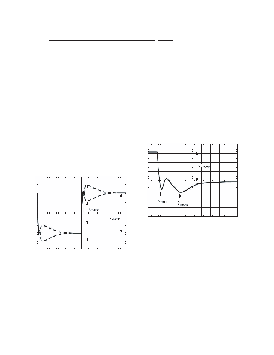
Initial Transient Setting
19. With dynamic load still set at maximum step size,
expand scope time scale to see 2s/div to 5s/div. You
will see a waveform that may have two overshoots and
one minor undershoot (see Figure 9). Here, VDROOP is
the nal desired value.
Figure 9. Transient Setting Waveform
20. If both overshoots are larger than desired, try making the
following adjustments in this order. (NOTE: If these
adjustments do not change the response, you are limited
by the output decoupling.) Check the output response
each time you make a change as well as the switching
nodes (to make sure it is still stable).
a. Make ramp resistor larger by 25% (RRAMP).
b. For VTRAN1, increase CB or increase switching fre-
quency.
c. For VTRAN2, increase RA and decrease CA by 25%.
21. For load release (see Figure 10), if VTRANREL is larger
than VTRAN1 (see Figure 9), you do not have enough
output capacitance. You will either need more capaci-
tance or to make the inductor values smaller (if you
change inductors, you need to start the design over using
the spreadsheet and this tuning procedure).
DCDRP
ACDRP
OLD
CS
NEW
CS
V
C
×
=
)
(
)
(
(38)
相關(guān)PDF資料 |
PDF描述 |
|---|---|
| FAN5037MX_NL | SWITCHING CONTROLLER, PDSO8 |
| FAN5037M_NL | SWITCHING CONTROLLER, PDSO8 |
| FAN5061M | SWITCHING CONTROLLER, 345 kHz SWITCHING FREQ-MAX, PDSO20 |
| FAN5201MSA | 6 A BATTERY CHARGE CONTROLLER, 275 kHz SWITCHING FREQ-MAX, PDSO24 |
| FAN5361UMP10X | SWITCHING REGULATOR, DSO6 |
相關(guān)代理商/技術(shù)參數(shù) |
參數(shù)描述 |
|---|---|
| FAN501MPX | 制造商:Fairchild Semiconductor Corporation 功能描述:PWM CONTROLLER - Tape and Reel |
| FAN5020_AAC3116B WAF | 制造商:Fairchild Semiconductor Corporation 功能描述: |
| FAN5021_AAC3026B WAF | 制造商:Fairchild Semiconductor Corporation 功能描述: |
| FAN5026 | 制造商:FAIRCHILD 制造商全稱:Fairchild Semiconductor 功能描述:Dual DDR/Dual-output PWM Controller |
| FAN5026_11 | 制造商:FAIRCHILD 制造商全稱:Fairchild Semiconductor 功能描述:Dual DDR / Dual-Output PWM Controller |
發(fā)布緊急采購(gòu),3分鐘左右您將得到回復(fù)。