- 您現(xiàn)在的位置:買賣IC網(wǎng) > PDF目錄362657 > ELANSC400-100AC (ADVANCED MICRO DEVICES INC) Single-Chip, Low-Power, PC/AT-Compatible Microcontrollers PDF資料下載
參數(shù)資料
| 型號(hào): | ELANSC400-100AC |
| 廠商: | ADVANCED MICRO DEVICES INC |
| 元件分類: | 微控制器/微處理器 |
| 英文描述: | Single-Chip, Low-Power, PC/AT-Compatible Microcontrollers |
| 中文描述: | 32-BIT, FLASH, 100 MHz, MICROCONTROLLER, PBGA292 |
| 封裝: | PLASTIC, BGA-292 |
| 文件頁(yè)數(shù): | 43/132頁(yè) |
| 文件大?。?/td> | 2400K |
| 代理商: | ELANSC400-100AC |
第1頁(yè)第2頁(yè)第3頁(yè)第4頁(yè)第5頁(yè)第6頁(yè)第7頁(yè)第8頁(yè)第9頁(yè)第10頁(yè)第11頁(yè)第12頁(yè)第13頁(yè)第14頁(yè)第15頁(yè)第16頁(yè)第17頁(yè)第18頁(yè)第19頁(yè)第20頁(yè)第21頁(yè)第22頁(yè)第23頁(yè)第24頁(yè)第25頁(yè)第26頁(yè)第27頁(yè)第28頁(yè)第29頁(yè)第30頁(yè)第31頁(yè)第32頁(yè)第33頁(yè)第34頁(yè)第35頁(yè)第36頁(yè)第37頁(yè)第38頁(yè)第39頁(yè)第40頁(yè)第41頁(yè)第42頁(yè)當(dāng)前第43頁(yè)第44頁(yè)第45頁(yè)第46頁(yè)第47頁(yè)第48頁(yè)第49頁(yè)第50頁(yè)第51頁(yè)第52頁(yè)第53頁(yè)第54頁(yè)第55頁(yè)第56頁(yè)第57頁(yè)第58頁(yè)第59頁(yè)第60頁(yè)第61頁(yè)第62頁(yè)第63頁(yè)第64頁(yè)第65頁(yè)第66頁(yè)第67頁(yè)第68頁(yè)第69頁(yè)第70頁(yè)第71頁(yè)第72頁(yè)第73頁(yè)第74頁(yè)第75頁(yè)第76頁(yè)第77頁(yè)第78頁(yè)第79頁(yè)第80頁(yè)第81頁(yè)第82頁(yè)第83頁(yè)第84頁(yè)第85頁(yè)第86頁(yè)第87頁(yè)第88頁(yè)第89頁(yè)第90頁(yè)第91頁(yè)第92頁(yè)第93頁(yè)第94頁(yè)第95頁(yè)第96頁(yè)第97頁(yè)第98頁(yè)第99頁(yè)第100頁(yè)第101頁(yè)第102頁(yè)第103頁(yè)第104頁(yè)第105頁(yè)第106頁(yè)第107頁(yè)第108頁(yè)第109頁(yè)第110頁(yè)第111頁(yè)第112頁(yè)第113頁(yè)第114頁(yè)第115頁(yè)第116頁(yè)第117頁(yè)第118頁(yè)第119頁(yè)第120頁(yè)第121頁(yè)第122頁(yè)第123頁(yè)第124頁(yè)第125頁(yè)第126頁(yè)第127頁(yè)第128頁(yè)第129頁(yè)第130頁(yè)第131頁(yè)第132頁(yè)
élanSC400 and élanSC410 Microcontrollers Data Sheet
43
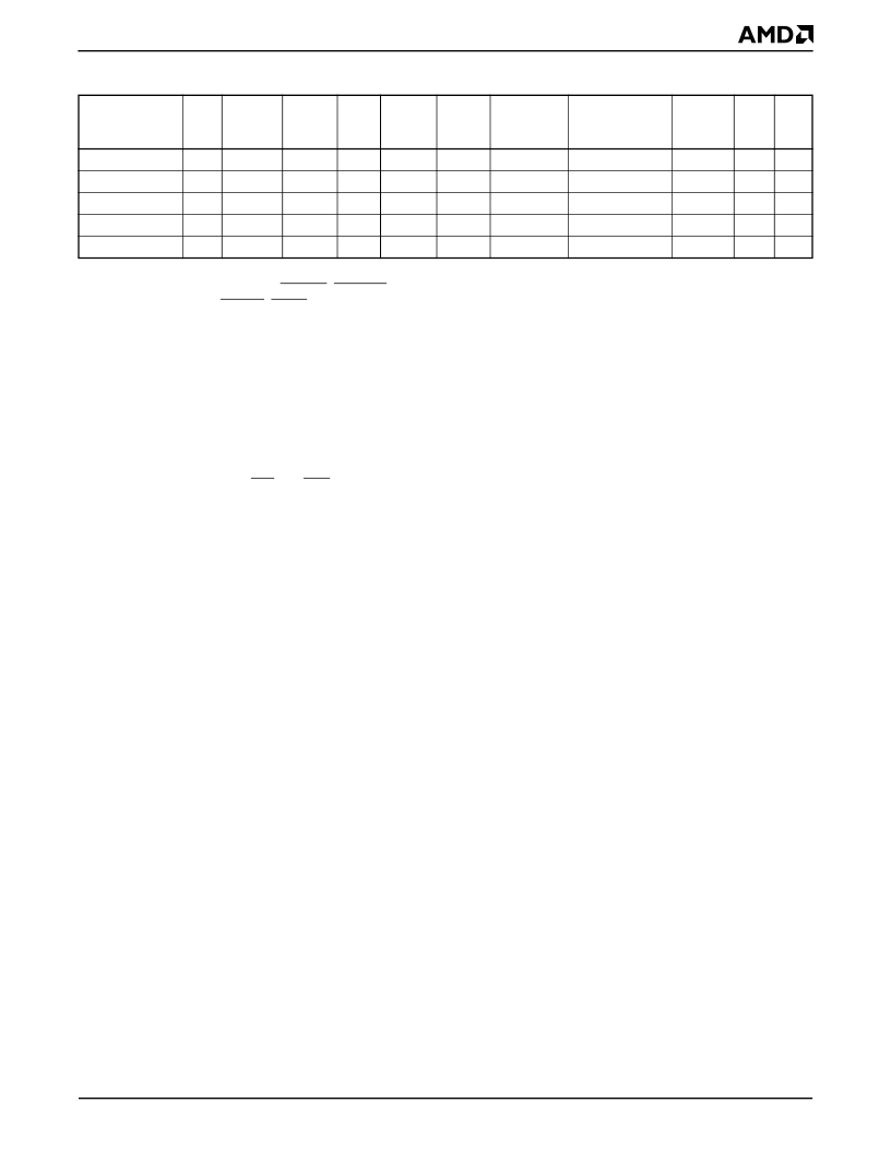
SD11 [D27]
SD12 [D28]
SD13 [D29]
SD14 [D30]
SD15 [D31]
K1
L1
L2
N1
L3
B [B]
B [B]
B [B]
B [B]
B [B]
C–E
4
C–E
4
C–E
4
C–E
4
C–E
4
70
70
70
70
70
V
CC
V
CC
V
CC
V
CC
V
CC
TS-PD
TS-PD
TS-PD
TS-PD
TS-PD
B-PPUD
B-PPUD
B-PPUD
B-PPUD
B-PPUD
I-PD
I-PD
I-PD
I-PD
I-PD
5
S
S
S
S
S
5
5
5
5
Notes:
1. Pin states for AEN, IOCHRDY, IOCS16, PDACK0
, PDRQ0, TC, and PIRQ1–PIRQ0 are listed in Table 9 on page 49.
Pin states for BALE, MCS16, SBHE, PDACK1, PDRQ1 and PIRQ7–PIRQ2 are listed in Table 14 on page 53.
2. The ISA control signals have three programmable options for Suspend mode:
–Driven High (inactive).
–Three-stated with no pullup or pulldown. This is useful when the ISA device is at 5 V and left powered in Suspend. The
board design should not drive 3.3-V signals into a 5-V device during Suspend because this can waste power. The system
designer should provide large pullup resistors to 5 V for each of these signals on the board if this configuration is
programmed.
– Three-stated with pulldown resistors when suspended with the intent of powering off the ISA device
(Power-Down Group C).
Be careful when handling IOR and IOW because they are shared with the PC Card sockets and may need to be buffered if
certain combinations of system components are powered up and off.
Summary:
These pins have built-in pulldown resistors that are invoked by:
–Suspend mode and the ISA interface is programmed to be powered off in Suspend mode (Power-Down Group C).
3. The SA bus, SA25–SA0, and the RSTDRV signal are three-stated with pulldowns in Suspend mode. This accommodates
having the ISA bus, PC Card sockets, VL bus, and ROM interfaces left powered on or powered off in Suspend mode.
Summary:
These pins have built-in pulldown resistors that are invoked by:
–Suspend mode.
4. C, D, and E output drives are programmable.
5. The combination of SD15–SD0 and D31–D16 on the same pins requires the signals to be pulled up in SD bus mode (for PC
compatibility) and pulled down in D bus mode (for consistency with D15–D0). Regardless of the mode the bus is in, the pins
are in the input state (i.e., they are still bidirectional and are not driven as outputs) and pulled down in Suspend mode.
These signals are pulled up or down automatically depending on whether the SD buffer is enabled or not (CFG3), and whether
the system is in Suspend mode or not.
Summary:
These pins have built-in pulldown and pullup resistors that are invoked by:
–Reset invokes the pulldown resistors.
–Suspend mode invokes the pulldown resistors.
–Operating (Hyper/High/Low/Temp Low-Speed modes): the pins will have pullups if the SD buffer control signals are
enabled, and have pulldowns otherwise.
Table 6.
Pin State Table—System Interface
1
(Continued)
Signal Name
[Alternate
Function]
Pin
#
Type
Output
Drive
Max
Load
(pF)
Supply
Reset
State
Normal
Operation
Suspend
State
Power
Down
Group
Note
5 V
相關(guān)PDF資料 |
PDF描述 |
|---|---|
| ELANSC520 | Microcontroller |
| ELC-10PR | HIGH-DENSITY SIGNAL CONDITIONERS 10-PACK PULSE SCALER |
| ELFC | AM Ladder Filters for Surface Mounting |
| ELFC455D | AM Ladder Filters for Surface Mounting |
| ELFC455E | AM Ladder Filters for Surface Mounting |
相關(guān)代理商/技術(shù)參數(shù) |
參數(shù)描述 |
|---|---|
| ELANSC400-100AI | 制造商:AMD 制造商全稱:Advanced Micro Devices 功能描述:Single-Chip, Low-Power, PC/AT-Compatible Microcontrollers |
| ELANSC400-33AC | 制造商:Advanced Micro Devices 功能描述:MCU 16-Bit/32-Bit Elan CISC ROMLess 3.3V 292-Pin BGA |
| ELANSC400-33AC-REVA3 | 制造商:Advanced Micro Devices 功能描述:MCU 16-Bit/32-Bit Elan CISC ROMLess 3.3V 292-Pin BGA |
| ELANSC400-33AI | 制造商:Advanced Micro Devices 功能描述:MCU 32-bit Elan RISC ROMLess 3.3V 292-Pin BGA |
| ELANSC400-33AIAD | 制造商:Advanced Micro Devices 功能描述: |
發(fā)布緊急采購(gòu),3分鐘左右您將得到回復(fù)。