- 您現(xiàn)在的位置:買賣IC網(wǎng) > PDF目錄11589 > DS2482S-100+T&R (Maxim Integrated Products)IC I2C TO 1WIRE BRIDGE 8SOIC PDF資料下載
參數(shù)資料
| 型號: | DS2482S-100+T&R |
| 廠商: | Maxim Integrated Products |
| 文件頁數(shù): | 1/24頁 |
| 文件大小: | 0K |
| 描述: | IC I2C TO 1WIRE BRIDGE 8SOIC |
| 產(chǎn)品培訓(xùn)模塊: | Lead (SnPb) Finish for COTS Obsolescence Mitigation Program |
| 標(biāo)準(zhǔn)包裝: | 1 |
| 系列: | * |
| 其它名稱: | DS2482S-100+T&RDKR |
AVAILABLE
Functional Diagrams
Pin Configurations appear at end of data sheet.
Functional Diagrams continued at end of data sheet.
UCSP is a trademark of Maxim Integrated Products, Inc.
For pricing, delivery, and ordering information, please contact Maxim Direct
at 1-888-629-4642, or visit Maxim’s website at www.maximintegrated.com.
General Description
The DS2482-100 is an I2C-to-1-Wire bridge device
that interfaces directly to standard (100kHz max) or fast
(400kHz max) I2C masters to perform bidirectional pro-
tocol conversion between the I2C master and any
downstream 1-Wire slave devices. Relative to any
attached 1-Wire slave device, the DS2482-100 is a
1-Wire master. Internal, factory-trimmed timers relieve
the system host processor from generating time-critical
1-Wire waveforms, supporting both standard and over-
drive 1-Wire communication speeds. To optimize
1-Wire waveform generation, the DS2482-100 performs
slew-rate control on rising and falling 1-Wire edges and
provides additional programmable features to match
drive characteristics to the 1-Wire slave environment.
Programmable, strong pullup features support 1-Wire
power delivery to 1-Wire devices such as EEPROMs
and sensors. The DS2482-100 combines these features
with an output to control an external MOSFET for
enhanced strong pullup application. The I2C slave
address assignment is controlled by two binary
address inputs, resolving potential conflicts with other
I2C slave devices in the system.
Applications
Features
I2C Host Interface Supports 100kHz and 400kHz
I2C Communication Speeds
1-Wire Master IO with Selectable Active or
Passive 1-Wire Pullup
Provides Reset/Presence, 8-Bit, Single-Bit, and
3-Bit 1-Wire IO Sequences
Standard and Overdrive 1-Wire Communication
Speeds
Slew-Controlled 1-Wire Edges
Strong 1-Wire Pullup Provided by an Internal Low-
Impedance Signal Path
PCTLZ Output to Optionally Control an External
MOSFET for Stronger Pullup Requirements
Two Address Inputs for I2C Address Assignment
Operating Range: 2.9V to 5.5V, -40°C to +85°C
8-Pin (150 mils) SO and 9-Bump WLP Packages
Single-Channel 1-Wire Master
Pin Configurations appear at end of data sheet.
Printers
Medical Instruments
Industrial Sensors
Cell Phones, PDAs
Ordering Information
+
Denotes a lead(Pb)-free/RoHS-compliant package.
T/T&R = Tape and reel.
PART
TEMP RANGE
PIN-PACKAGE
DS2482S-100+
-40
°C to +85°C
8 SO (150 mils)
DS2482S-100+T&R
-40
°C to +85°C
8 SO (150 mils)
DS2482X-100+T
-40
°C to +85°C
9 WLP (2.5k pieces)
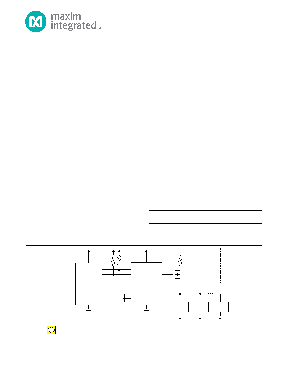
Typical Operating Circuit
1-Wire is a registered trademark of Maxim Integrated Products, Inc.
DS2482-100
SDA
SCL
AD1
AD0
PCTLZ
IO
RP*
*RP = I2C PULLUP RESISTOR (SEE THE APPLICATIONS INFORMATION SECTION FOR RP SIZING).
VCC
CURRENT-LIMITING
RESISTOR
REFER TO APPLICATION
NOTE 4206
OPTIONAL
CIRCUITRY
1-Wire LINE
μC
(I2C PORT)
1-Wire
DEVICE
1-Wire
DEVICE
1-Wire
DEVICE
19-4930; Rev 9; 1/12
DS2482-100
相關(guān)PDF資料 |
PDF描述 |
|---|---|
| PIC12F629T-I/MD | IC PIC MCU FLASH 1KX14 8DFN |
| PIC24F04KA201-I/SO | IC PIC MCU FLASH 512KX4 20-SOIC |
| PIC16F722-I/MV | IC MCU 8BIT 3.5KB FLASH 28UQFN |
| PIC16F616-I/ST | IC PIC MCU FLASH 2KX14 14TSSOP |
| PIC16F687-E/SS | IC PIC MCU FLASH 2KX14 20SSOP |
相關(guān)代理商/技術(shù)參數(shù) |
參數(shù)描述 |
|---|---|
| DS2482S-101+ | 制造商:MAXIM 制造商全稱:Maxim Integrated Products 功能描述:Single-Channel 1-Wire Master with Sleep Mode |
| DS2482S-101+TR | 制造商:MAXIM 制造商全稱:Maxim Integrated Products 功能描述:Single-Channel 1-Wire Master with Sleep Mode |
| DS2482S-800 | 功能描述:接口 - 專用 RoHS:否 制造商:Texas Instruments 產(chǎn)品類型:1080p60 Image Sensor Receiver 工作電源電壓:1.8 V 電源電流:89 mA 最大功率耗散: 最大工作溫度:+ 85 C 安裝風(fēng)格:SMD/SMT 封裝 / 箱體:BGA-59 |
| DS2482S-800/T&R | 功能描述:接口 - 專用 RoHS:否 制造商:Texas Instruments 產(chǎn)品類型:1080p60 Image Sensor Receiver 工作電源電壓:1.8 V 電源電流:89 mA 最大功率耗散: 最大工作溫度:+ 85 C 安裝風(fēng)格:SMD/SMT 封裝 / 箱體:BGA-59 |
| DS2482S-800+ | 功能描述:接口 - 專用 8 Ch 1-Wire Master RoHS:否 制造商:Texas Instruments 產(chǎn)品類型:1080p60 Image Sensor Receiver 工作電源電壓:1.8 V 電源電流:89 mA 最大功率耗散: 最大工作溫度:+ 85 C 安裝風(fēng)格:SMD/SMT 封裝 / 箱體:BGA-59 |
發(fā)布緊急采購,3分鐘左右您將得到回復(fù)。