- 您現(xiàn)在的位置:買賣IC網(wǎng) > PDF目錄376805 > DMC73C167 8Bit Single Chip Microcontroller PDF資料下載
參數(shù)資料
| 型號(hào): | DMC73C167 |
| 英文描述: | 8Bit Single Chip Microcontroller |
| 中文描述: | 8位單芯片微控制器 |
| 文件頁(yè)數(shù): | 38/90頁(yè) |
| 文件大小: | 742K |
| 代理商: | DMC73C167 |
第1頁(yè)第2頁(yè)第3頁(yè)第4頁(yè)第5頁(yè)第6頁(yè)第7頁(yè)第8頁(yè)第9頁(yè)第10頁(yè)第11頁(yè)第12頁(yè)第13頁(yè)第14頁(yè)第15頁(yè)第16頁(yè)第17頁(yè)第18頁(yè)第19頁(yè)第20頁(yè)第21頁(yè)第22頁(yè)第23頁(yè)第24頁(yè)第25頁(yè)第26頁(yè)第27頁(yè)第28頁(yè)第29頁(yè)第30頁(yè)第31頁(yè)第32頁(yè)第33頁(yè)第34頁(yè)第35頁(yè)第36頁(yè)第37頁(yè)當(dāng)前第38頁(yè)第39頁(yè)第40頁(yè)第41頁(yè)第42頁(yè)第43頁(yè)第44頁(yè)第45頁(yè)第46頁(yè)第47頁(yè)第48頁(yè)第49頁(yè)第50頁(yè)第51頁(yè)第52頁(yè)第53頁(yè)第54頁(yè)第55頁(yè)第56頁(yè)第57頁(yè)第58頁(yè)第59頁(yè)第60頁(yè)第61頁(yè)第62頁(yè)第63頁(yè)第64頁(yè)第65頁(yè)第66頁(yè)第67頁(yè)第68頁(yè)第69頁(yè)第70頁(yè)第71頁(yè)第72頁(yè)第73頁(yè)第74頁(yè)第75頁(yè)第76頁(yè)第77頁(yè)第78頁(yè)第79頁(yè)第80頁(yè)第81頁(yè)第82頁(yè)第83頁(yè)第84頁(yè)第85頁(yè)第86頁(yè)第87頁(yè)第88頁(yè)第89頁(yè)第90頁(yè)
38
8Bit Single Chip Microcontroller
DMC73C167
5.5.1 Timer 1
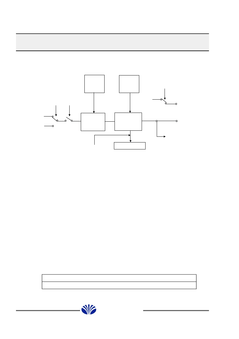
Figure 5-5. Timer 1 Schematic Diagram
Timer 1 is a 16-bit timer that contains a 5-bit prescaler and a 16-bit decrementer. The clock
source of Timer 1 is determined by bit 5 of T1CTL0 (T1SRC, P22.5).
Writing 0 to the T1SRC bit selects the internally generated Fosc/4 clock and places the timer/
event counter in real-timer clock mode. A T1SRC bit of 1 selects the external clock source
and places the timer/event counter in event counter mode.
Bit 7 of the T1CTL0 register is the START bit for Timer 1. When 0 is written to the START
bit, the timer chain is disabled or frozen at the current count value. When 1 is written to the
START bit, regardless of whether it was previously a 0 or a 1, the prescaler and counter
decrementers are loaded with the corresponding latch values and the timer/event counter
operation begins.
When the prescaler and counter decrement through zero together, an interrupt flag is set,
and the prescaler and counter decrementers are immediately and automatically reloaded
with the corresponding latch values of the reload registers.
The interrupt level generated by Timer 1 is INT2_0. Timer 1 has a 16-bit capture latch
associated with INT1(A3) that captures the current value of the counter whenever INT1 (port
A3) is activated.
5.5.1.1 Timer 1 Control Registers
Table 5-18. P20 0114h T1MSD Timer 1 MSB Data
Bit
R
7
6
5
4
3
2
1
0
16-bit Timer 1 MSB Decrementer Value
W
16-bit Timer 1 MSB Reload Register
££á££×££
Pin A1
(I/O Port A1)
Prescaler
Reload
Register
16- bit
Reload
Register
5- bit
Prescaler
Fosc/4
T1SRC
START
Capture Latch
A3 (External INT1)
Timer 1
Interrupt
(INT2_0)
Toggle Out
Normal
Port Out
Pin B0
T1OUT
16- bit
Decrementer
相關(guān)PDF資料 |
PDF描述 |
|---|---|
| DMC73C168 | 8Bit Single Chip Microcontroller |
| DMC80C49 | CMOS SINGLE-COMPONENT 8-BIT MICROCOMPUTER |
| DMCA1CHP | TRANSISTOR | MOSFET | ARRAY | N-CHANNEL | 20V V(BR)DSS | 50MA I(D) | CHIP |
| DMCB1CHP | TRANSISTOR | MOSFET | N-CHANNEL | 30V V(BR)DSS | 50MA I(D) | CHIP |
| DMCB2CHP | TRANSISTOR | MOSFET | N-CHANNEL | 30V V(BR)DSS | 50MA I(D) | CHIP |
相關(guān)代理商/技術(shù)參數(shù) |
參數(shù)描述 |
|---|---|
| DMC73C168 | 制造商:DAEWOO 制造商全稱:DAEWOO 功能描述:8Bit Single Chip Microcontroller |
| DMC757 | 制造商:Daniels Manufacturing Corporation (DMC) 功能描述:CONNECTOR |
| DMC-8/16-15 | 制造商:Brady Corporation 功能描述: |
| DMC-8/16-30 | 制造商:Brady Corporation 功能描述: |
| DMC80C49 | 制造商:DAEWOO 制造商全稱:DAEWOO 功能描述:CMOS SINGLE-COMPONENT 8-BIT MICROCOMPUTER |
發(fā)布緊急采購(gòu),3分鐘左右您將得到回復(fù)。