- 您現(xiàn)在的位置:買賣IC網(wǎng) > PDF目錄376804 > DM9801A PDF資料下載
參數(shù)資料
| 型號: | DM9801A |
| 文件頁數(shù): | 48/60頁 |
| 文件大小: | 605K |
| 代理商: | DM9801A |
第1頁第2頁第3頁第4頁第5頁第6頁第7頁第8頁第9頁第10頁第11頁第12頁第13頁第14頁第15頁第16頁第17頁第18頁第19頁第20頁第21頁第22頁第23頁第24頁第25頁第26頁第27頁第28頁第29頁第30頁第31頁第32頁第33頁第34頁第35頁第36頁第37頁第38頁第39頁第40頁第41頁第42頁第43頁第44頁第45頁第46頁第47頁當前第48頁第49頁第50頁第51頁第52頁第53頁第54頁第55頁第56頁第57頁第58頁第59頁第60頁
DM9801A
1M Home Phoneline Network Physical Layer Single Chip Transceiver
48
Final
Version: DM9801A-DS-F01
May 30, 2001
Data Symbol RLL25 Encoding
The Run Length Limit (RLL25)code was developed for the
Home Networking PHY. It produces highest bit rate for a
given value of ISBI (Inter-Symbol Blanking Interval) and
TIC size. In a manor similar to run length limited disk
coding, RLL27 encodes data bits in groups of various
sizes, specifically, 3, 4, 5, and 6 bits. Pulse positions are
assigned to the encoded bit groups in a manor that
causes more data bits to be encoded in positions that ate
farther apart. This keeps both the average and minimum
bit rates higher.
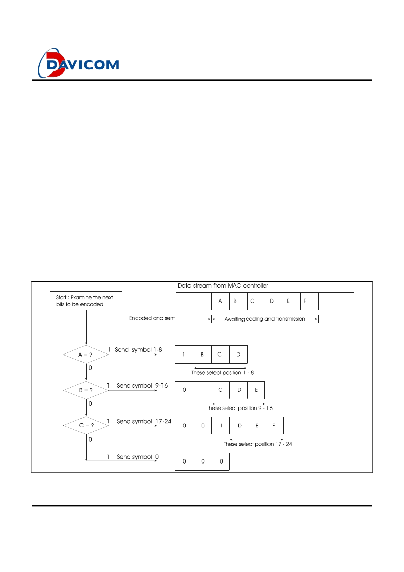
RLL25 codes data by traversing a tree as shown in figure
26 below. Assuming that successive data bits to be
encoded are labeled A, B, C, D…,etc. The encoding
process begins at the root node and proceeds as follows:
If the first bit (bit A) is a one, the next 3 bits (B, C, and
D) select which one of the eight positions (1-8) is
transmitted. The encoding process then continues at
the root node.
If bit A is a zero and bit B is a one, the next 3 bits (C,
D, and E) select which one of eight positions (9-16) is
transmitted. The encoding process then continues at
the root node.
If bit A is a zero, bit B is a zero, and bit C is a one, the
next 3 bits (D, E, and F) select which one of eight
positions (17-24) is transmitted. The encoding
process then continues at the root node.
Finally, if bits A, B, and C are all zeros, position 0 is
transmitted. The encoding process then continues at
the root node.
As a result, Symbol 0 encodes the 3-bit data pattern 000,
positions 1-8 encode the 4-bit data pattern 1BCD,
positions 9-16 encode the 5-bit data pattern 01CDE, and
positions 17-24 encode the 6-bit data pattern 001DEF. If
the data encoded is random, 50% of the positions used
will be for 4-bit data patterns, 25% will be for 5-bit data
patterns, 12.5% will be for 6-bit data patterns, and 12.5%
will be for 3-bit data patterns.
RLL 25 Coding Tree
Figure 26
相關(guān)PDF資料 |
PDF描述 |
|---|---|
| DM9801E | 1M home Phonrline Network Physical Layer Single Chip Transceiver |
| DMA2271 | Consumer IC |
| DMA2280 | Consumer IC |
| DMA2281 | Consumer IC |
| DMA2275 | DMA 2275, DMA 2286 C/D/D2-MAC Descrambler |
相關(guān)代理商/技術(shù)參數(shù) |
參數(shù)描述 |
|---|---|
| DM9801AE | 制造商:DAVICOM 制造商全稱:DAVICOM 功能描述:1M Home Phoneline Network Physical Layer Single Chip Transceiver |
| DM9801E | 制造商:未知廠家 制造商全稱:未知廠家 功能描述:1M home Phonrline Network Physical Layer Single Chip Transceiver |
| DM9B | 功能描述:數(shù)字萬用表 4000 COUNT AUTO RoHS:否 制造商:Tektronix 產(chǎn)品:Multimeters 類型:Bench 準確性:0.04 % 電壓范圍:2 V to 2 kV 電阻范圍: 電容范圍: 顯示計數(shù): 頻率:10 Hz to 45 Hz, 850 Hz to 1 MHz 測距: 真均方根值: 數(shù)據(jù)保持: |
| D-M9B | 制造商:SMC Corporation of America 功能描述:Sensor, solid state, direct mount, grommet connection, for MX/MH/CQ2/NCQ2/NCQ8 制造商:SMC 功能描述:2-Wire Auto Switch for 24Vdc Relay/PLC |
| D-M9BA | 制造商:SMC Corporation of America 功能描述:Autoswitch, water resistant, 2 wire, horizontal |
發(fā)布緊急采購,3分鐘左右您將得到回復。