- 您現(xiàn)在的位置:買賣IC網(wǎng) > PDF目錄379075 > CY7C1464AV33 (Cypress Semiconductor Corp.) 36-Mbit (1M x 36/2M x 18/512K x 72) Pipelined SRAM with NoBL Architecture(帶NoBL結(jié)構(gòu)的36-Mbit (1M x 36/2M x 18/512K x 72) Pipelined SRAM) PDF資料下載
參數(shù)資料
| 型號(hào): | CY7C1464AV33 |
| 廠商: | Cypress Semiconductor Corp. |
| 英文描述: | 36-Mbit (1M x 36/2M x 18/512K x 72) Pipelined SRAM with NoBL Architecture(帶NoBL結(jié)構(gòu)的36-Mbit (1M x 36/2M x 18/512K x 72) Pipelined SRAM) |
| 中文描述: | 36兆位(1米x 36/2M x 18/512K × 72)流水線的SRAM架構(gòu)的總線延遲(帶總線延遲結(jié)構(gòu)的36兆位(1米x 36/2M x 18/512K × 72)流水線的SRAM) |
| 文件頁(yè)數(shù): | 6/27頁(yè) |
| 文件大小: | 469K |
| 代理商: | CY7C1464AV33 |
第1頁(yè)第2頁(yè)第3頁(yè)第4頁(yè)第5頁(yè)當(dāng)前第6頁(yè)第7頁(yè)第8頁(yè)第9頁(yè)第10頁(yè)第11頁(yè)第12頁(yè)第13頁(yè)第14頁(yè)第15頁(yè)第16頁(yè)第17頁(yè)第18頁(yè)第19頁(yè)第20頁(yè)第21頁(yè)第22頁(yè)第23頁(yè)第24頁(yè)第25頁(yè)第26頁(yè)第27頁(yè)
CY7C1460AV33
CY7C1462AV33
CY7C1464AV33
Document #: 38-05353 Rev. *D
Page 6 of 27
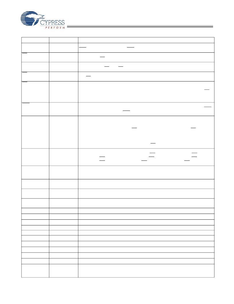
CLK
Input-
Clock
Input-
Clock Input
. Used to capture all synchronous inputs to the device. CLK is qualified with
CEN. CLK is only recognized if CEN is active LOW.
Chip Enable 1 Input, active LOW
. Sampled on the rising edge of CLK. Used in conjunction
with CE
2
and CE
3
to select/deselect the device.
Chip Enable 2 Input, active HIGH
. Sampled on the rising edge of CLK. Used in
conjunction with CE
1
and CE
3
to select/deselect the device.
Chip Enable 3 Input, active LOW
. Sampled on the rising edge of CLK. Used in conjunction
with CE
1
and
CE
2
to select/deselect the device.
Output Enable, active LOW
. Combined with the synchronous logic block inside the device
to control the direction of the I/O pins. When LOW, the I/O pins are allowed to behave as
outputs. When deasserted HIGH, I/O pins are tri-stated, and act as input data pins. OE is
masked during the data portion of a write sequence, during the first clock when emerging
from a deselected state and when the device has been deselected.
Clock Enable Input, active LOW
. When asserted LOW the clock signal is recognized by
the SRAM. When deasserted HIGH the clock signal is masked. Since deasserting CEN
does not deselect the device, CEN can be used to extend the previous cycle when required.
Bidirectional Data I/O lines
. As inputs, they feed into an on-chip data register that is
triggered by the rising edge of CLK. As outputs, they deliver the data contained in the
memory location specified by A
X
during the previous clock rise of the read cycle. The
direction of the pins is controlled by OE and the internal control logic. When OE is asserted
LOW, the pins can behave as outputs. When HIGH, DQ
a
–DQ
d
are placed in a tri-state
condition. The outputs are automatically tri-stated during the data portion of a write
sequence, during the first clock when emerging from a deselected state, and when the
device is deselected, regardless of the state of OE.
Bidirectional Data Parity I/O lines
. Functionally, these signals are identical to DQ
[31:0]
.
During write sequences, DQP
a
is controlled by BW
a
, DQP
b
is controlled by BW
b
, DQP
c
is
controlled by BW
c
, and DQP
d
is controlled by BW
d
, DQP
e
is controlled by BW
e
, DQP
f
is
controlled by BW
f
, DQP
g
is controlled by BW
g
, DQP
h
is controlled by BW
h
.
Mode Input
. Selects the burst order of the device. Tied HIGH selects the interleaved burst
order. Pulled LOW selects the linear burst order. MODE should not change states during
operation. When left floating MODE will default HIGH, to an interleaved burst order.
Serial data-out to the JTAG circuit
. Delivers data on the negative edge of TCK.
CE
1
Synchronous
Input-
Synchronous
Input-
Synchronous
Input-
Asynchronous
CE
2
CE
3
OE
CEN
Input-
Synchronous
DQ
a
DQ
b
DQ
c
DQ
d
DQ
e
DQ
f
DQ
g
DQ
h
DQP
a,
DQP
b,
DQP
c,
DQP
d
DQP
e,
DQP
f
DQP
g,
DQP
h
MODE
I/O-
Synchronous
I/O-
Synchronous
Input Strap Pin
TDO
JTAG serial output
Synchronous
JTAG serial input
Synchronous
Test Mode Select
Synchronous
JTAG-Clock
Power Supply
I/O Power Supply
Power supply for the I/O circuitry
.
Ground
Ground for the device
. Should be connected to ground of the system.
N/A
No connects
. This pin is not connected to the die.
N/A
Not connected to the die
. Can be tied to any voltage level.
N/A
Not connected to the die
. Can be tied to any voltage level.
N/A
Not connected to the die
. Can be tied to any voltage level.
N/A
Not connected to the die
. Can be tied to any voltage level.
N/A
Not connected to the die
. Can be tied to any voltage level.
Input-
Asynchronous
condition with data integrity preserved. During normal operation, this pin can be connected
to V
SS
or left floating. ZZ pin has an internal pull-down.
TDI
Serial data-In to the JTAG circuit
. Sampled on the rising edge of TCK.
TMS
This pin controls the Test Access Port state machine
. Sampled on the rising edge of
TCK.
Clock input to the JTAG circuitry
.
Power supply inputs to the core of the device
.
TCK
V
DD
V
DDQ
V
SS
NC
NC/72M
NC
/144M
NC
/288M
NC
/576M
NC
/1G
ZZ
ZZ “sleep” Input
. This active HIGH input places the device in a non-time critical “sleep”
Pin Definitions
(continued)
Pin Name
I/O Type
Pin Description
相關(guān)PDF資料 |
PDF描述 |
|---|---|
| CY7C1462AV33 | 36-Mbit (1M x 36/2M x 18/512K x 72) Pipelined SRAM with NoBL Architecture(帶NoBL結(jié)構(gòu)的36-Mbit (1M x 36/2M x 18/512K x 72) Pipelined SRAM) |
| CY7C1472V33-167AXI | 72-Mbit (2M x 36/4M x 18/1M x 72) Pipelined SRAM with NoBL Architecture |
| CY7C1472V33-167BZXI | 72-Mbit (2M x 36/4M x 18/1M x 72) Pipelined SRAM with NoBL Architecture |
| CY7C1472V33-200AXC | 72-Mbit (2M x 36/4M x 18/1M x 72) Pipelined SRAM with NoBL Architecture |
| CY7C1472V33-200BZC | 72-Mbit (2M x 36/4M x 18/1M x 72) Pipelined SRAM with NoBL Architecture |
相關(guān)代理商/技術(shù)參數(shù) |
參數(shù)描述 |
|---|---|
| CY7C1464AV33-167BGI | 功能描述:靜態(tài)隨機(jī)存取存儲(chǔ)器 512Kx72 3.3V NoBL PL 靜態(tài)隨機(jī)存取存儲(chǔ)器 RoHS:否 制造商:Cypress Semiconductor 存儲(chǔ)容量:16 Mbit 組織:1 M x 16 訪問(wèn)時(shí)間:55 ns 電源電壓-最大:3.6 V 電源電壓-最小:2.2 V 最大工作電流:22 uA 最大工作溫度:+ 85 C 最小工作溫度:- 40 C 安裝風(fēng)格:SMD/SMT 封裝 / 箱體:TSOP-48 封裝:Tray |
| CY7C146-55JC | 制造商:Cypress Semiconductor 功能描述:SRAM Chip Async Dual 5V 16K-Bit 2K x 8 55ns 52-Pin PLCC 制造商:Cypress Semiconductor 功能描述:2K X 8 DUAL-PORT SRAM, 55 ns, PQCC52 |
| CY7C146-55JCT | 制造商:Cypress Semiconductor 功能描述: |
| CY7C146-55JXC | 功能描述:靜態(tài)隨機(jī)存取存儲(chǔ)器 5V 2Kx8 COM Dual Port 靜態(tài)隨機(jī)存取存儲(chǔ)器 RoHS:否 制造商:Cypress Semiconductor 存儲(chǔ)容量:16 Mbit 組織:1 M x 16 訪問(wèn)時(shí)間:55 ns 電源電壓-最大:3.6 V 電源電壓-最小:2.2 V 最大工作電流:22 uA 最大工作溫度:+ 85 C 最小工作溫度:- 40 C 安裝風(fēng)格:SMD/SMT 封裝 / 箱體:TSOP-48 封裝:Tray |
| CY7C146-55JXCT | 功能描述:靜態(tài)隨機(jī)存取存儲(chǔ)器 5V 2Kx8 COM Dual Port 靜態(tài)隨機(jī)存取存儲(chǔ)器 RoHS:否 制造商:Cypress Semiconductor 存儲(chǔ)容量:16 Mbit 組織:1 M x 16 訪問(wèn)時(shí)間:55 ns 電源電壓-最大:3.6 V 電源電壓-最小:2.2 V 最大工作電流:22 uA 最大工作溫度:+ 85 C 最小工作溫度:- 40 C 安裝風(fēng)格:SMD/SMT 封裝 / 箱體:TSOP-48 封裝:Tray |
發(fā)布緊急采購(gòu),3分鐘左右您將得到回復(fù)。