- 您現(xiàn)在的位置:買賣IC網(wǎng) > PDF目錄170207 > CS8414-CS (Electronic Theatre Controls, Inc.) 96 KHZ DIGITAL AUDIO RECEIVER PDF資料下載
參數(shù)資料
| 型號: | CS8414-CS |
| 廠商: | Electronic Theatre Controls, Inc. |
| 英文描述: | 96 KHZ DIGITAL AUDIO RECEIVER |
| 中文描述: | 96 kHz的數(shù)字音頻接收器 |
| 文件頁數(shù): | 2/38頁 |
| 文件大小: | 646K |
| 代理商: | CS8414-CS |
第1頁當(dāng)前第2頁第3頁第4頁第5頁第6頁第7頁第8頁第9頁第10頁第11頁第12頁第13頁第14頁第15頁第16頁第17頁第18頁第19頁第20頁第21頁第22頁第23頁第24頁第25頁第26頁第27頁第28頁第29頁第30頁第31頁第32頁第33頁第34頁第35頁第36頁第37頁第38頁
CS8413 CS8414
10
DS240F1
pulses are generated the first time that condition oc-
curs. If the status register is not read, further in-
stances of that same condition will not generate
another interrupt. ERF is the error flag bit and is set
when the ERF pin goes high. It is an OR’ing of the
errors listed in status register 2, bits 0 through 4,
AND’ed with their associated interrupt enable bits
in IEnable register 2.
SLIP is only valid when the audio port is in slave
mode (FSYNC and SCK are inputs to the CS8413).
This flag is set when an audio sample is dropped or
reread because the audio data output from the part
is at a different frequency than the data received
from the transmission line. CCHG is set when any
bit in channel status bytes 0 through 3, stored in the
buffer, changes from one block to the next. In buff-
er modes 0 and 1, only one channel of channel sta-
tus data is buffered, so CCHG is only affected by
that channel. (CS2/CS1 in CR1 selects which chan-
nel is buffered.) In buffer mode 2 both channels are
buffered, so both channels affect CCHG. This bit is
updated after each byte (0 to 3) is written to the
buffer. The two most significant bits in SR1,
CRCE/CRC1 and CSDIF/CRC2, are dual function
flags. In buffer modes 0 and 1, they are CRCE and
CSDIF, and in buffer mode 2, they are CRC1 and
CRC2. In buffer modes 0 and 1, the channel select-
ed by the CS2/CS1 bit is stored in RAM and CRCE
indicates that a CRC error occurred in that channel.
CSDIF is set if there is any difference between the
channel status bits of each channel. In buffer mode
2 channel status from both channels is buffered,
with CRC1 indicating a CRC error in channel 1 and
CRC2 indicating a CRC error in channel 2. CRCE,
CRC1, and CRC2 are updated at the block bound-
ary. Block boundary violations also cause CRC1,2
or CRCE to be set.
IEnable register 1, which occupies the same ad-
dress space as status register 1, contains interrupt
enable bits for all conditions in status register 1. A
“1” in a bit location enables the same bit location in
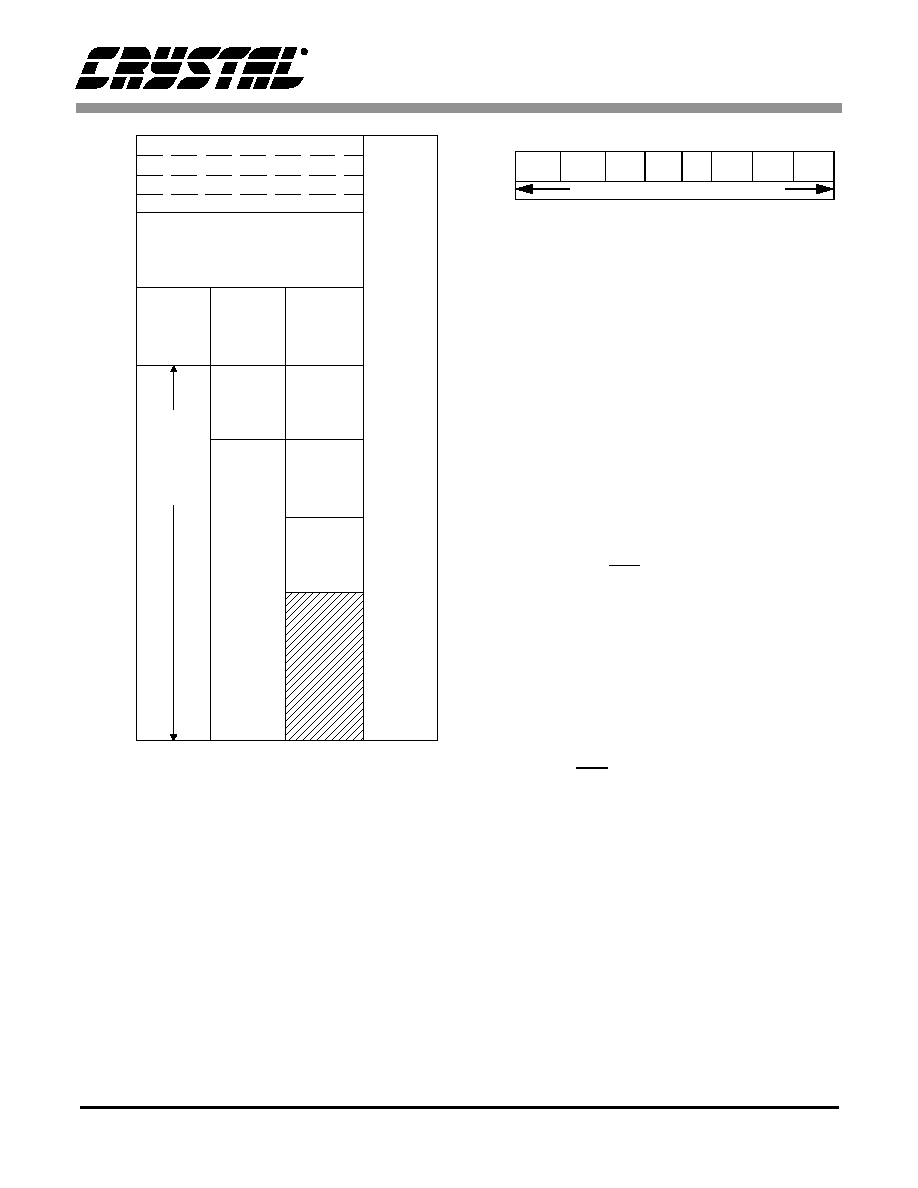
01
2
3
User Data
1st Four
Bytes of
C. S. Data
1st Four
Bytes of
C. S. Data
1st Four
Bytes of
Left C. S.
Data
Auxiliary
Data
Last
20 Bytes
Channel
Status
Data
Status 1 / IEnable 1
C. S.
Data
Left
C. S.
Data
Right
C. S.
Data
1st Four
Bytes of
Right
C. S. Data
U
N
D
E
F
I
N
E
D
A
D
R
E
S
Memory Mode
0
1
2
3
4
5
6
7
8
9
A
B
C
D
E
F
10
11
12
13
14
15
16
17
18
19
1A
1B
1C
1D
1E
1F
Control Register 1
Control Register 2
Status 2 / IEnable 2
Figure 5. CS8413 Buffer Memory Map
SR1:
CSDIF:
CS different between sub-frames. Buffer modes 0 & 1
CRC2:
CRC Error - sub-frame 2. Buffer mode 2 only.
CRCE:
CRC Error - selected sub-frame. Buffer modes 0 & 1
CRC1:
CRC Error - sub-frame 1. Buffer mode 2 only.
CCHG:
Channel Status changed
SLIP:
Slipped an audio sample
ERF:
Error Flag. ORing of all errors in SR2.
FLAG2:
High for first four bytes of channel status
FLAG1:
Memory mode dependent - See Figure 11.
FLAG0:
High for last two bytes of user data.
IER1: Enables the corresponding bit in SR1.
A “1” enables the interrupt. A “0” masks the interrupt.
X:00
7
6
5
4
3
2
1
0
SR1.
CSDIF/
CRC2
CRCE/
CRC1
CCHG
SLIP
ERF FLAG2 FLAG1 FLAG0
IER1.
INTERRUPT ENABLE BITS FOR ABOVE
Figure 6. Status/IEnable Register 1
SR1:
CSDIF:
CS different between sub-frames. Buffer modes 0 & 1
CRC2:
CRC Error - sub-frame 2. Buffer mode 2 only.
CRCE:
CRC Error - selected sub-frame. Buffer modes 0 & 1
CRC1:
CRC Error - sub-frame 1. Buffer mode 2 only.
CCHG:
Channel Status changed
SLIP:
Slipped an audio sample
ERF:
Error Flag. ORing of all errors in SR2.
FLAG2:
High for first four bytes of channel status
FLAG1:
Memory mode dependent - See Figure 11.
FLAG0:
High for last two bytes of user data.
IER1: Enables the corresponding bit in SR1.
A “1” enables the interrupt. A “0” masks the interrupt.
X:00
7
6
5
4
3
2
1
0
SR1.
CSDIF/
CRC2
CRCE/
CRC1
CCHG
SLIP
ERF FLAG2 FLAG1 FLAG0
IER1.
INTERRUPT ENABLE BITS FOR ABOVE
相關(guān)PDF資料 |
PDF描述 |
|---|---|
| CSB7152-01 | 70 V, SILICON, PIN DIODE |
| CSBFB1M00J58-R1 | CERAMIC RESONATOR, 1 MHz |
| CSBLA400KECE-B0 | CERAMIC RESONATOR, 0.4 MHz |
| CSC09ST-224K-B246 | 1 ELEMENT, 220000 uH, GENERAL PURPOSE INDUCTOR |
| CSC1004-1252 | INTERCONNECTION DEVICE |
相關(guān)代理商/技術(shù)參數(shù) |
參數(shù)描述 |
|---|---|
| CS8414-CSR | 制造商:Rochester Electronics LLC 功能描述: 制造商:Cirrus Logic 功能描述: |
| CS8414-CSZ | 功能描述:音頻 DSP IC 96 kHz Digital Audio Receivers RoHS:否 制造商:Texas Instruments 工作電源電壓: 電源電流: 工作溫度范圍: 安裝風(fēng)格: 封裝 / 箱體: 封裝:Tube |
| CS8414-CSZ/A | 制造商:Cirrus Logic 功能描述: |
| CS8414-CSZR | 功能描述:音頻 DSP IC 96 kHz Digital Audio Receivers RoHS:否 制造商:Texas Instruments 工作電源電壓: 電源電流: 工作溫度范圍: 安裝風(fēng)格: 封裝 / 箱體: 封裝:Tube |
| CS8415A | 制造商:CIRRUS 制造商全稱:Cirrus Logic 功能描述:96 kHz DIGITAL AUDIO INTERFACE RECEIVER |
發(fā)布緊急采購,3分鐘左右您將得到回復(fù)。