- 您現(xiàn)在的位置:買賣IC網(wǎng) > PDF目錄170207 > CS8414-CS (Electronic Theatre Controls, Inc.) 96 KHZ DIGITAL AUDIO RECEIVER PDF資料下載
參數(shù)資料
| 型號: | CS8414-CS |
| 廠商: | Electronic Theatre Controls, Inc. |
| 英文描述: | 96 KHZ DIGITAL AUDIO RECEIVER |
| 中文描述: | 96 kHz的數(shù)字音頻接收器 |
| 文件頁數(shù): | 17/38頁 |
| 文件大小: | 646K |
| 代理商: | CS8414-CS |
第1頁第2頁第3頁第4頁第5頁第6頁第7頁第8頁第9頁第10頁第11頁第12頁第13頁第14頁第15頁第16頁當前第17頁第18頁第19頁第20頁第21頁第22頁第23頁第24頁第25頁第26頁第27頁第28頁第29頁第30頁第31頁第32頁第33頁第34頁第35頁第36頁第37頁第38頁
CS8413 CS8414
24
DS240F1
Multifunction Pins
There are seven multifunction pins which contain
either error and received frequency information, or
channel status information, selectable by SEL.
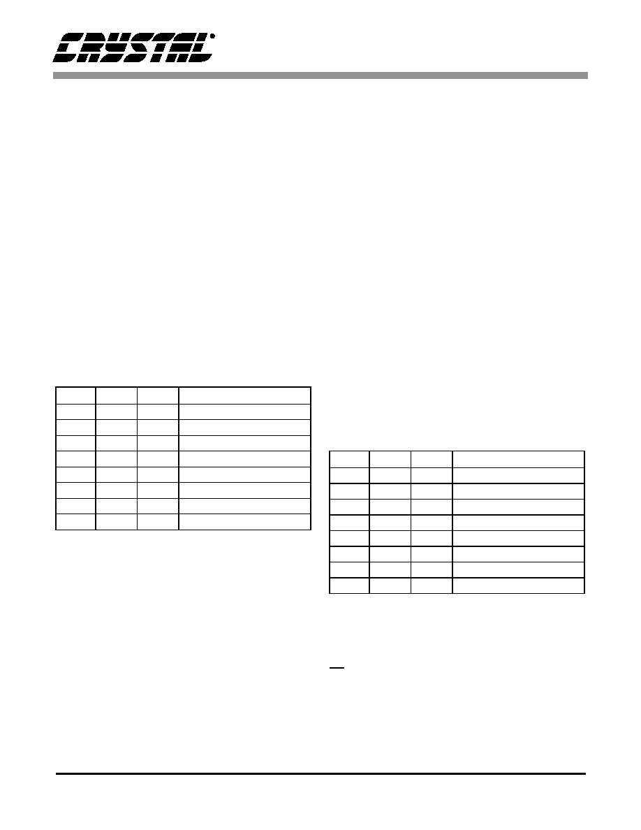
Error and Frequency Reporting
When SEL is low, error and received frequency in-
formation are selected. The error information is en-
coded on pins E2, E1, and E0, and is decoded as
shown in Table 5. When an error occurs, the corre-
sponding error code is latched. Clearing is then ac-
complished by bringing SEL high for more than
eight MCK cycles. The errors have a priority asso-
ciated with their error code, with validity having
the lowest priority and no lock having the highest
priority. Since only one code can be displayed, the
error with the highest priority that occurred since
the last clearing will be selected.
Table 5. Error Decoding
The validity flag indicates that the validity bit for a
previous sample was high since the last clearing of
the error codes. The slipped sample error can only
occur when FSYNC and SCK of the audio serial
port are inputs. In this case, if FSYNC is asynchro-
nous to the received data rate, periodically a stereo
sample will be dropped or reread depending on
whether the read rate is slower or faster than the re-
ceived data rate. When this occurs, the slipped sam-
ple error code will appear on the ‘E’ pins. The CRC
error is updated at the beginning of a channel status
block, and is only valid when the professional for-
mat of channel status data is received. This error is
indicated when the CS8414 calculated CRC value
does not match the CRC byte of the channel status
block or when a block boundary changes (as in re-
moving samples while editing). The parity error oc-
curs when the incoming sub-frame does not have
even parity as specified by the standards. The bi-
phase coding error indicates a biphase coding vio-
lation occurred. The no lock error indicates that the
PLL is not locked onto the incoming data stream.
The received frequency information is encoded on
pins F2, F1, and F0, and is decoded as shown in Ta-
ble 6. The on-chip frequency comparator compares
the received clock frequency to an externally sup-
plied 6.144 MHz clock which is input on the FCK
pin. The ‘F’ pins are updated three times during a
channel status block including prior to the rising
edge of CBL. CBL may be used to externally latch
the ‘F’ pins. The clock on FCK must be valid for
two thirds of a block for the ‘F’ pins to be accurate.
The ‘F’ pins are invalid when the PLL is out of
lock.
Table 6. Sample Frequency Decoding
Channel Status Reporting
When SEL is high, channel status is displayed on
C0, and Ca-Ce for the channel selected by CS12. If
CS12 is low, channel status for sub-frame 1 is dis-
played, and if CS12 is high, channel status for sub-
frame 2 is displayed. The contents of Ca-Ce depend
E2
E1
E0
Error
00
0
No Error
0
1
Validity Bit High
0
1
0
Reserved
0
1
Slipped Sample
1
0
CRC Error (PRO only)
10
1
Parity Error
1
0
Bi-phase Coding Error
1
No Lock
F2
F1
F0
Sample Frequency
0
Out of Range
0
1
reserved
0
1
0
reserved
01
1
96 kHz ±4%
1
0
88.2 kHz ±4%
1
0
1
48 kHz ±4%
1
0
44.1 kHz ±4%
1
32 kHz ±4%
相關(guān)PDF資料 |
PDF描述 |
|---|---|
| CSB7152-01 | 70 V, SILICON, PIN DIODE |
| CSBFB1M00J58-R1 | CERAMIC RESONATOR, 1 MHz |
| CSBLA400KECE-B0 | CERAMIC RESONATOR, 0.4 MHz |
| CSC09ST-224K-B246 | 1 ELEMENT, 220000 uH, GENERAL PURPOSE INDUCTOR |
| CSC1004-1252 | INTERCONNECTION DEVICE |
相關(guān)代理商/技術(shù)參數(shù) |
參數(shù)描述 |
|---|---|
| CS8414-CSR | 制造商:Rochester Electronics LLC 功能描述: 制造商:Cirrus Logic 功能描述: |
| CS8414-CSZ | 功能描述:音頻 DSP IC 96 kHz Digital Audio Receivers RoHS:否 制造商:Texas Instruments 工作電源電壓: 電源電流: 工作溫度范圍: 安裝風格: 封裝 / 箱體: 封裝:Tube |
| CS8414-CSZ/A | 制造商:Cirrus Logic 功能描述: |
| CS8414-CSZR | 功能描述:音頻 DSP IC 96 kHz Digital Audio Receivers RoHS:否 制造商:Texas Instruments 工作電源電壓: 電源電流: 工作溫度范圍: 安裝風格: 封裝 / 箱體: 封裝:Tube |
| CS8415A | 制造商:CIRRUS 制造商全稱:Cirrus Logic 功能描述:96 kHz DIGITAL AUDIO INTERFACE RECEIVER |
發(fā)布緊急采購,3分鐘左右您將得到回復。