- 您現(xiàn)在的位置:買賣IC網(wǎng) > PDF目錄1890 > AD5520JSTZ (Analog Devices Inc)IC PPMU SNGL-CH 64-LQFP PDF資料下載
參數(shù)資料
| 型號: | AD5520JSTZ |
| 廠商: | Analog Devices Inc |
| 文件頁數(shù): | 6/24頁 |
| 文件大?。?/td> | 0K |
| 描述: | IC PPMU SNGL-CH 64-LQFP |
| 標(biāo)準(zhǔn)包裝: | 1 |
| 類型: | 每引腳參數(shù)測量單元(PPMU) |
| 應(yīng)用: | 自動測試設(shè)備 |
| 安裝類型: | 表面貼裝 |
| 封裝/外殼: | 64-LQFP |
| 供應(yīng)商設(shè)備封裝: | 64-LQFP(10x10) |
| 包裝: | 托盤 |
| 產(chǎn)品目錄頁面: | 775 (CN2011-ZH PDF) |
| 配用: | EVAL-AD5520EBZ-ND - BOARD EVAL FOR AD5520 |
AD5520
Rev. B | Page 14 of 24
INTERFACE
The AD5520 PPMU is controlled via a number of digital inputs,
which are discussed in detail in the following sections. All
inputs are TTL-compatible. CS is used to select the device while
STB (active low input) latches data available on the other digital
inputs and updates any required digital outputs. The rising edge
of STB triggers sequence inputs. The remaining digital inputs
control the function of the PMU. They also determine which
measure mode the PMU is in, the compensation capacitor used,
and the selected current range.
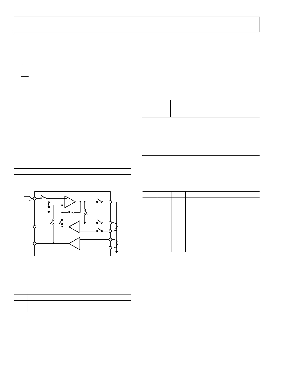
STANDBY MODE
The AD5520 can be placed into standby mode via the standby
logic input. In this mode, the force amplifier is disconnected
from the force input (FIN). In addition, the switch in series with
the force output pins (FOHx) is opened, and the current
measure amplifier is disconnected from the sense resistors. The
voltage measure amplifier is still connected across the DUT;
therefore, DUT voltage measurements may still be made while
in standby mode. Figure 21 shows the configuration of the
PMU while in standby mode.
Table 5. Standby Mode
Standby
Function
Low
Normal Force Mode
High
Standby Mode
DAC
MEASIHx
MEASIL
MEASVH
MEASVL
FOHx
RS
DUT
FIN
MEASIOUT
MEASVOUT
G = 16
G = 1
03701-021
Figure 21. PMU in Standby Mode
FORCE VOLTAGE OR FORCE CURRENT
FSEL is an input that determines whether the PPMU forces a
voltage or current.
Table 6. FSEL Function
FSEL
Function
Low
Voltage Force and Current Clamp with MEASIOUT Voltage
High
Current Force and Voltage Clamp with MEASVOUT Voltage
MEASURED PARAMETER
MEASOUT is a muxed output that tracks the sensed parameter.
MSEL (digital input) connects the MEASOUT to the output of
the current sense amplifier or the voltage sense amplifier,
depending on which is the measured parameter of interest.
The MEASOUT pin is connected back to an ADC to allow the
measured value to be converted to a digital code.
Table 7. MEASOUT Connected to Voltage or Current
MSEL
Function
Low
MEASOUT = DUT Voltage
High
MEASOUT = DUT Current
The MEASOUT pin can also be made high impedance through
the MOEB logic input.
Table 8. MOEB Allows MEASOUT to Go High Impedance
MOEB
Function
Low
Enable MEASOUT Output
High
Hi-Z MEASOUT Output
CURRENT RANGES
A number of current ranges are possible with the AD5520. The
AM0, AM1, and AM2 pins are digital inputs used to establish
full-scale current range of the PMU.
Table 9. Selection of Current Range
AM0
AM1
AM2
Function
Low
Current Range MODE0 (4 μA)
High
Low
Current Range MODE1 (40 μA)
Low
High
Low
Current Range MODE2 (400 μA)
High
Low
Current Range MODE3 (4 mA)
Low
High
Current Range MODE4
(External Buffer Mode)
High
Low
High
Current Range MODE5
(External Buffer Mode)
Low
High
Standby (Same as STANDBY = High)
High
Standby (Same as STANDBY = High)
RS SELECTION
The AD5520 is designed to ensure the voltage drop across each
of the RS resistors is less than ±500 mV when maximum current
is flowing through them. To support other current ranges, these
sense resistor values can be changed. The force amplifier can
drive a maximum of 6 mA. It is not recommended to increase
the maximum current above the nominal range.
The two external current ranges use an external buffer to drive
higher current. The example in Figure 26 uses 40 mA and
160 mA ranges. These ranges can be changed to suit user
requirements for a high current range.
相關(guān)PDF資料 |
PDF描述 |
|---|---|
| AD5522JSVUZ | IC PMU QUAD 16BIT DAC 80-TQFP |
| AD5532ABC-5 | IC DAC 14BIT 32CH 74-CSPBGA |
| AD5532HSABC | IC DAC 14BIT 32CH 74-CSPBGA |
| AD5535ABCZ | IC DAC 14BIT 32CHAN 124CSPBGA |
| AD5547BRU | IC DAC 16BIT DUAL 38-TSSOP |
相關(guān)代理商/技術(shù)參數(shù) |
參數(shù)描述 |
|---|---|
| AD5520JSTZ-REEL | 制造商:AD 制造商全稱:Analog Devices 功能描述:Per Pin Parametric Measurement Unit/Source Measure Unit |
| AD5520JSTZ-REEL1 | 制造商:AD 制造商全稱:Analog Devices 功能描述:Per Pin Parametric Measurement Unit/Source Measure Unit |
| AD5521JST | 制造商:Analog Devices 功能描述: |
| AD5521JSTZ | 制造商:Analog Devices 功能描述: |
| AD5522 | 制造商:AD 制造商全稱:Analog Devices 功能描述:Quad Parametric Measurement Unit With Integrated 16-Bit Level Setting DACs |
發(fā)布緊急采購,3分鐘左右您將得到回復(fù)。