- 您現(xiàn)在的位置:買賣IC網(wǎng) > PDF目錄25569 > 9LPR501SGLFT (INTEGRATED DEVICE TECHNOLOGY INC) SPECIALTY MICROPROCESSOR CIRCUIT, PDSO64 PDF資料下載
參數(shù)資料
| 型號(hào): | 9LPR501SGLFT |
| 廠商: | INTEGRATED DEVICE TECHNOLOGY INC |
| 元件分類: | 微控制器/微處理器 |
| 英文描述: | SPECIALTY MICROPROCESSOR CIRCUIT, PDSO64 |
| 封裝: | 6.10 MM, 0.50 MM PITCH, ROHS COMPLIANT, MO-153, TSSOP-64 |
| 文件頁數(shù): | 20/21頁 |
| 文件大小: | 197K |
| 代理商: | 9LPR501SGLFT |

IDTTM/ICSTM
64-pin CK505 w/Fully Integrated Voltage Regulator
1118N—05/19/11
Advance Information
ICS9LPR501
64-PIN CK505 W/FULLY INTEGRATED VOLTAGE REGULATOR
8
Datasheet
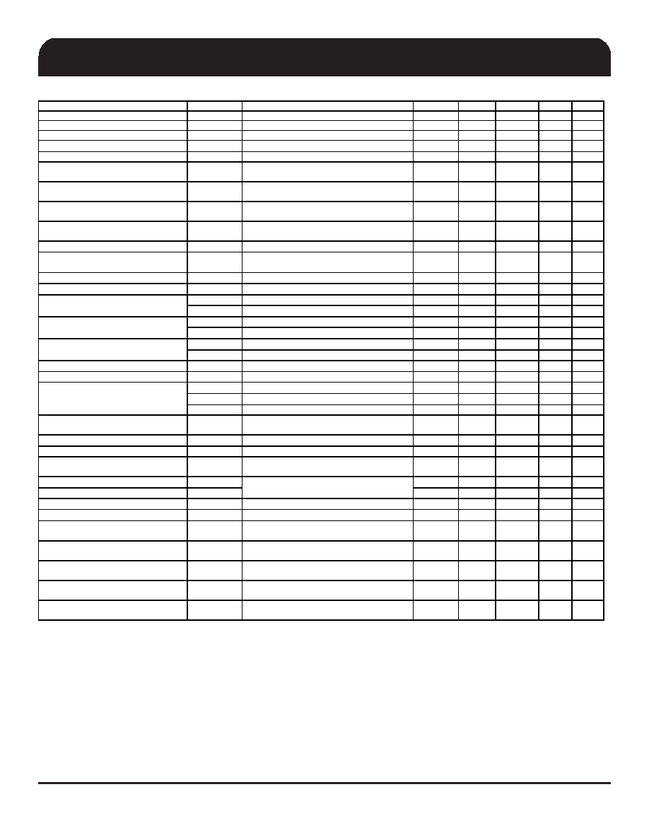
Electrical Characteristics - Input/Supply/Common Output DC Parameters
PAR AMETER
SYMBOL
CONDITIONS
MIN
TYP
MAX
UNITS
Notes
Ambient Operating Temp
Tambient
-
0
25
70
°C
Supply Voltage
VDDxxx
Supply Voltage
3.135
3.3
3.465
V
Supply Voltage
VDDxxx_IO
Low-Voltage Differential I/O Supply
0.9975
1.05
3.465
V
10
Input H igh Voltage
VIHSE
Single-ended 3.3V inputs
2.2
VDD + 0.3
V
3
Input Low Voltage
VILSE
Single-ended 3.3V inputs
VSS - 0.3
0.8
V
3
Low Threshold Input-
High Voltage FSC = Test Mode
VIH_FSC_TEST
3.3 V +/-5%
2
V
8
Low Threshold Input-
FSC = '1' Voltage
VIH _FSC_1
3.3 V +/-5%
0.7
1.5
V
8
Low Threshold Input-
FSA,FSB = '1' Voltage
VIH_FSAB_1
3.3 V +/-5%
0.7
V
Low Threshold Input-
Low Voltage
VIL_FS
3.3 V +/-5%
VSS - 0.3
0.35
V
Input Leakage Current
IIN
VIN = VD D , VIN = GND
-5
5
uA
2
Input Leakage Current
IINRES
Inputs with pull up or pull down resistors
VIN = VD D , VIN = GND
-200
200
uA
Output High Voltage
VOHSE
Single-ended outputs, IOH = -1mA
2.4
V
Output Low Voltage
VOL SE
Single-ended outputs, IOL = 1 mA
0.4
V
IDDOP3.3
Full Active, CL = Full load; IDD 3.3V
135
200
mA
IDDOPIO
Full Active, CL = Full load; IDD IO
72
80
mA
IDDiAMT3 .3
M1 mode, 3.3V R ail
53
65
mA
IDDiAMTIO
M1 Mode, IO Rail
7
10
mA
IDDPD3.3
Power down mode, 3.3V Rail, B63b0 = '1'
22
25
mA
IDDPDIO
Power down mode, IO Rail
0.01
0.1
mA
Input Frequency
Fi
VDD = 3.3 V
14.31818
15
MHz
Pin Inductance
Lpin
7nH
CIN
Logic Inputs
1.5
5
pF
COUT
Output pin capacitance
6
pF
CINX
X1 & X2 pins
6
pF
Clk Stabilization
TSTAB
From VDD Pow er-U p or de-assertion of PD to
1st clock
1.2
1.8
ms
Tdrive_CR_off
TDRCR OFF
Output stop after C R deasserted
400
ns
Tdrive_CR_on
TDRCRON
Output run after CR asserted
0
us
Tdrive_CPU
TDRSRC
CPU output enable after
PCI_STOP# de-assertion
10
ns
Tfall_SE
TFALL
10
ns
1
Trise_SE
TRISE
10
ns
1
SMBus Voltage
VDD
2.7
5.5
V
Low-level Output Voltage
VOLSMB
@ IPULLUP
0.4
V
C urrent sinking at
VOLSMB = 0.4 V
I
PUL LUP
SMB Data Pin
4
mA
SCLK/SD ATA
Clock/Data Rise Time
TRI2 C
(Max VIL - 0.15) to
(Min VIH + 0.15)
1000
ns
SCLK/SDATA
Clock/Data Fall Time
TFI2C
(Min VIH + 0.15) to
(Max VIL - 0.15)
300
ns
Maximum SMBus Operating Frequency
FSMBUS
100
kHz
Spread Spectrum Modulation Frequency
fSSMOD
Triangular Modulation
30
32.54
33
kHz
NOTES on D C Parameters: (unless otherwise noted, guaranteed by design and characterization, not 100% tested in production).
1Signal is required to be monotonic in this region.
2 input leakage current does not include inputs with pull-up or pull-down resistors
3 3.3V referenced inputs are: PCI_STOP#, CPU_STOP#, TME, SRC5_EN, ITP_EN, SCLKL, SDATA, TESTMODE, TESTSEL, CKPWRGD and CR# inputs if selected.
4 Intentionally blank
5 Maximum VIH is not to exceed VDD
6 Human Body Model
7 Operation under these conditions is neither implied, nor guaranteed.
8 Frequency Select pins which have tri-level input
Powerdown C urrent
Input Capacitance
Fall/rise time of all 3.3V control inputs from 20-
80%. Inputs must be monot onic
Operating Supply Current
iAMT Mode Current
相關(guān)PDF資料 |
PDF描述 |
|---|---|
| 9LPR501YGT | SPECIALTY MICROPROCESSOR CIRCUIT, PDSO64 |
| 9LPR502YGLFT | SPECIALTY MICROPROCESSOR CIRCUIT, PDSO56 |
| 9LPRS365BKLFT | SPECIALTY MICROPROCESSOR CIRCUIT, PQCC64 |
| 9LPRS365BGLFT | SPECIALTY MICROPROCESSOR CIRCUIT, PDSO64 |
| 9LPRS436CKLF | SPECIALTY MICROPROCESSOR CIRCUIT, PQCC48 |
相關(guān)代理商/技術(shù)參數(shù) |
參數(shù)描述 |
|---|---|
| 9LPR501YGLFT | 制造商:IDT 制造商全稱:Integrated Device Technology 功能描述:64-PIN CK505 W/FULLY INTEGRATED VOLTAGE REGULATOR |
| 9LPR502HGLF | 制造商:Integrated Device Technology Inc 功能描述:PC CLOCK, TSSOP56 - Rail/Tube |
| 9LPR502HGLFT | 制造商:Integrated Device Technology Inc 功能描述:PC CLOCK, TSSOP56 - Rail/Tube |
| 9LPR502SGLF | 功能描述:時(shí)鐘合成器/抖動(dòng)清除器 PC MAIN CLOCK RoHS:否 制造商:Skyworks Solutions, Inc. 輸出端數(shù)量: 輸出電平: 最大輸出頻率: 輸入電平: 最大輸入頻率:6.1 GHz 電源電壓-最大:3.3 V 電源電壓-最小:2.7 V 封裝 / 箱體:TSSOP-28 封裝:Reel |
| 9LPR502SGLFT | 功能描述:時(shí)鐘合成器/抖動(dòng)清除器 PC MAIN CLOCK RoHS:否 制造商:Skyworks Solutions, Inc. 輸出端數(shù)量: 輸出電平: 最大輸出頻率: 輸入電平: 最大輸入頻率:6.1 GHz 電源電壓-最大:3.3 V 電源電壓-最小:2.7 V 封裝 / 箱體:TSSOP-28 封裝:Reel |
發(fā)布緊急采購,3分鐘左右您將得到回復(fù)。