- 您現(xiàn)在的位置:買賣IC網(wǎng) > PDF目錄122717 > 935261475512 (NXP SEMICONDUCTORS) 8 CHANNEL(S), 500K bps, SERIAL COMM CONTROLLER, PQCC84 PDF資料下載
參數(shù)資料
| 型號: | 935261475512 |
| 廠商: | NXP SEMICONDUCTORS |
| 元件分類: | 微控制器/微處理器 |
| 英文描述: | 8 CHANNEL(S), 500K bps, SERIAL COMM CONTROLLER, PQCC84 |
| 封裝: | PLASTIC, MO-047AF, SOT-189-3, LCC-84 |
| 文件頁數(shù): | 22/59頁 |
| 文件大小: | 383K |
| 代理商: | 935261475512 |
第1頁第2頁第3頁第4頁第5頁第6頁第7頁第8頁第9頁第10頁第11頁第12頁第13頁第14頁第15頁第16頁第17頁第18頁第19頁第20頁第21頁當前第22頁第23頁第24頁第25頁第26頁第27頁第28頁第29頁第30頁第31頁第32頁第33頁第34頁第35頁第36頁第37頁第38頁第39頁第40頁第41頁第42頁第43頁第44頁第45頁第46頁第47頁第48頁第49頁第50頁第51頁第52頁第53頁第54頁第55頁第56頁第57頁第58頁第59頁
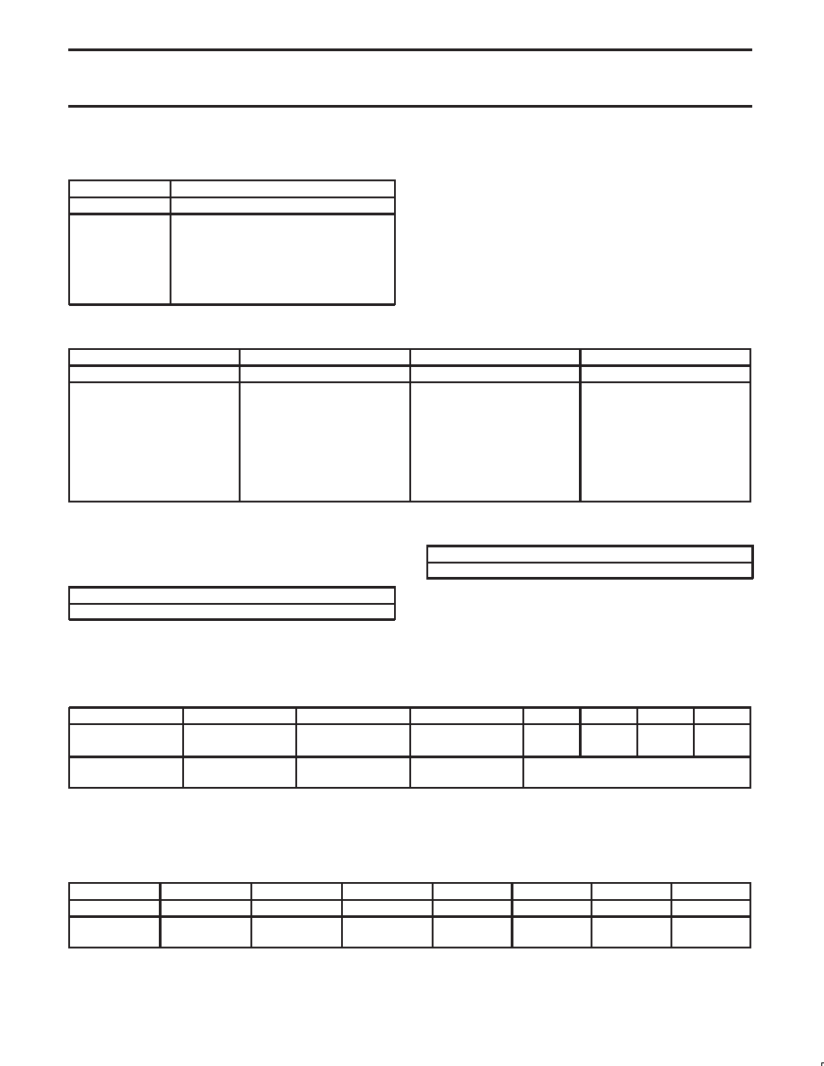
Philips Semiconductors
Product specification
SC28L198
Octal UART for 3.3V and 5V supply voltage
1999 Jan 14
29
Table 32. GIBCR – Global Interrupting Byte Count
Register
Bits 7:4
Bits 3:0
Reserved
Channel byte count code
0000 = 1 AND RxRDY status set for RxFIFO
0000 = 1 AND TxRDY status set for TxD
0001 = 2
0010 = 3
.
1111 = 16
A register associated with the interrupting channel as defined in the
CIR. Its numerical value equals
the number of bytes minus 1 (count – 1) ready for transfer to the
transmitter or transfer from the receiver. It is undefined for other
types of interrupts
Table 33. Global Interrupting Type Register
Bit 7:6
Bit 5
Bit 4:3
Bit 2:0
Receiver Interrupt
Transmitter Interrupt
Reserved
Other types
0x – not receiver
10 – with receive errors
11 – w/o receive errors
0 – not transmitter
1 – transmitter interrupt
read b’00
000 – not ”other” type
001 – Change of State
010 – Address Recognition
Event
011 – Xon/Xoff status
100 – Not used
101 – Break Change
11x – do not occur
A register associated with the interrupting channel as defined in the
CIR. It contains the type of interrupt code for all interrupts.
Table 34. GRxFIFO – Global RxFIFO Register
Bits 7:0
8 data bits of RxFIFO. MSBs set to 0 for 7, 6, 5 bit data
The RxFIFO of the channel indicated in the CIR channel field.
Undefined when the CIR interrupt context is not a receiver interrupt.
Global TxFIFO Register
Table 35. GTxFIFO – Global TxFIFO Register
Bits 7:0
8 data bits of TxFIFO. MSBs not used for 7, 6, 5 bit data
The TxFIFO of the channel indicated in the CIR channel field.
Undefined when the CIR interrupt context is not a transmitter
interrupt. Writing to the GTxFIFO when the current interrupt is not a
transmitter event may result in the characters being transmitted on a
different channel than intended.
Table 36. IPR – Input Port Register,
Bit 7
Bit 6
Bit 7
Bit 6
Bit 3
Bit 2
Bit 1
Bit 0
I/O3
change
I/O2
change
I/O1
change
I/O0
change
I/O3
state
I/O2
state
I/O1
state
I/O0
state
0 – no change
1 – change
0 – no change
1 – change
0 – no change
1 – change
0 – no change
1 – change
The actual logic level at the I/O pin.
1 = high level; 0 =– low level.
This register may be read to determine the current level of the I/O
pins and examine the output of the change detectors assigned to
each pin. If the change detection is not enabled or if the pin is
configured as an output, the associated change field will read b’0.
Table 37. I/OPIOR – I/O Port Interrupt and Output Register
Bit 7
Bit 6
Bit 5
Bit 4
Bit 3
Bit 2
Bit 1
Bit 0
I/O3 enable
I/O2 enable
I/O1 enable
I/O0 enable
I/O3 output
I/O2 output
I/O1 output
I/O0 output
0 – disable
1 – enable
0 – disable
1 – enable
0 – disable
1 – enable
0 – disable
1 – enable
OPR[3]
OPR[2]
OPR[1]
OPR[0]
I/OPIOR[7:4] bits activate the input change of state detectors. If a
pin is configured as an output, a b’1 value written to a I/O field has
no effect.
I/OPIOR[3:0] bits hold the datum which is the inverse of the datum
driven to its associated I/O pin when the I/OPCR control bits for that
pin are programmed to b’01.
相關(guān)PDF資料 |
PDF描述 |
|---|---|
| 9LPRS365BKLF | SPECIALTY MICROPROCESSOR CIRCUIT, PQCC64 |
| 91W-G28AC-6-CG9 | SINGLE COLOR DISPLAY CLUSTER, GREEN, 7.1 mm |
| 91W-G5AC-6-CW0 | SINGLE COLOR DISPLAY CLUSTER, GREEN, 7.1 mm |
| 94W-EAY2-S0 | SINGLE COLOR LED, AMBER, 8.5 mm |
| 94W-EAY28H-CA0 | SINGLE COLOR LED, AMBER, 8.5 mm |
相關(guān)代理商/技術(shù)參數(shù) |
參數(shù)描述 |
|---|---|
| 935262025112 | 制造商:NXP Semiconductors 功能描述:SUB ONLY IC |
| 935262217118 | 制造商:NXP Semiconductors 功能描述:Real Time Clock Serial 8-Pin SO T/R |
| 935264217557 | 制造商:NXP Semiconductors 功能描述:SUB ONLY IC |
| 935267356112 | 制造商:NXP Semiconductors 功能描述:IC TEA1507PN |
| 935268081112 | 制造商:NXP Semiconductors 功能描述:SUB ONLY IC |
發(fā)布緊急采購,3分鐘左右您將得到回復(fù)。