- 您現(xiàn)在的位置:買賣IC網(wǎng) > PDF目錄369347 > 784215A (NEC Corp.) MOS INTEGRATED CIRCUIT PDF資料下載
參數(shù)資料
| 型號: | 784215A |
| 廠商: | NEC Corp. |
| 英文描述: | MOS INTEGRATED CIRCUIT |
| 中文描述: | 馬鞍山集成電路 |
| 文件頁數(shù): | 42/100頁 |
| 文件大?。?/td> | 564K |
| 代理商: | 784215A |
第1頁第2頁第3頁第4頁第5頁第6頁第7頁第8頁第9頁第10頁第11頁第12頁第13頁第14頁第15頁第16頁第17頁第18頁第19頁第20頁第21頁第22頁第23頁第24頁第25頁第26頁第27頁第28頁第29頁第30頁第31頁第32頁第33頁第34頁第35頁第36頁第37頁第38頁第39頁第40頁第41頁當(dāng)前第42頁第43頁第44頁第45頁第46頁第47頁第48頁第49頁第50頁第51頁第52頁第53頁第54頁第55頁第56頁第57頁第58頁第59頁第60頁第61頁第62頁第63頁第64頁第65頁第66頁第67頁第68頁第69頁第70頁第71頁第72頁第73頁第74頁第75頁第76頁第77頁第78頁第79頁第80頁第81頁第82頁第83頁第84頁第85頁第86頁第87頁第88頁第89頁第90頁第91頁第92頁第93頁第94頁第95頁第96頁第97頁第98頁第99頁第100頁

Data Sheet U14121EJ2V0DS00
42
μ
PD784214A, 784215A, 784216A, 784217A, 784218A, 784214AY, 784215AY, 784216AY, 784217AY, 784218AY
7.5 A/D Converter
An A/D converter converts an analog signal input into a digital signal. This microcontroller is provided with an A/D
converter with a resolution of 8 bits and eight channels (ANI0 to ANI7).
This A/D converter is of successive approximation type and the result of conversion is stored in an 8-bit A/D
conversion result register (ADCR).
The A/D converter can be started in the following two ways:
Hardware start
Conversion is started by trigger input (P03).
Software start
Conversion is started by setting the A/D converter mode register (ADM).
One analog input channel is selected from ANI0 to ANI7 for A/D conversion. When A/D conversion is started by
means of hardware start, conversion is stopped after it has been completed. When conversion is started by means
of software start, A/D conversion is repeatedly executed. Each time conversion has been completed, an interrupt
request (INTAD) is generated.
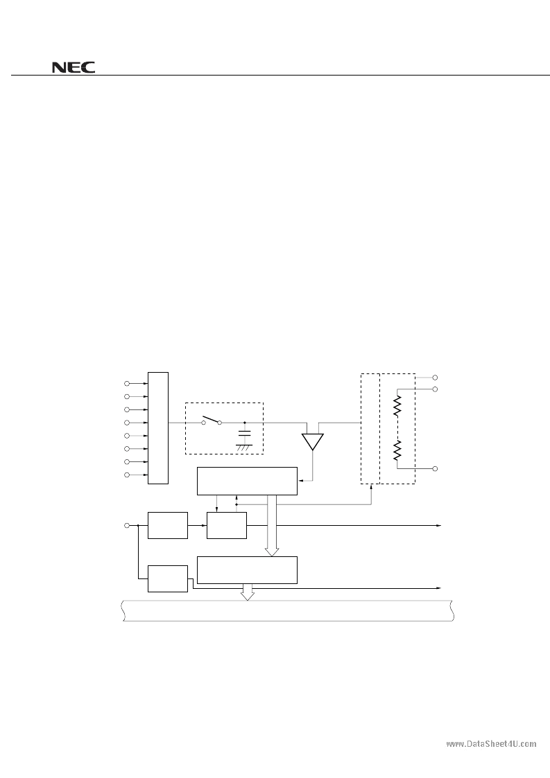
Figure 7-7. Block Diagram of A/D Converter
ANI0
ANI1
ANI2
ANI3
ANI4
ANI5
ANI6
ANI7
Sample & hold circuit
Series resistor string
Voltage comparator
Successive approximation
register (SAR)
A/D conversion result register
(ADCR)
Controller
Edge
detector
INTP3/P03
INTAD
INTP3
AV
SS
AV
REF0
AV
DD
Internal bus
S
T
Edge
detector
www.DataSheet4U.com
相關(guān)PDF資料 |
PDF描述 |
|---|---|
| 784215AY | MOS INTEGRATED CIRCUIT |
| 784216A | MOS INTEGRATED CIRCUIT |
| 784216AY | MOS INTEGRATED CIRCUIT |
| 784217A | MOS INTEGRATED CIRCUIT |
| 784217AY | MOS INTEGRATED CIRCUIT |
相關(guān)代理商/技術(shù)參數(shù) |
參數(shù)描述 |
|---|---|
| 784215AY | 制造商:NEC 制造商全稱:NEC 功能描述:MOS INTEGRATED CIRCUIT |
| 784216A | 制造商:NEC 制造商全稱:NEC 功能描述:MOS INTEGRATED CIRCUIT |
| 784216AY | 制造商:NEC 制造商全稱:NEC 功能描述:MOS INTEGRATED CIRCUIT |
| 784217A | 制造商:NEC 制造商全稱:NEC 功能描述:MOS INTEGRATED CIRCUIT |
| 784217AY | 制造商:NEC 制造商全稱:NEC 功能描述:MOS INTEGRATED CIRCUIT |
發(fā)布緊急采購,3分鐘左右您將得到回復(fù)。