- 您現(xiàn)在的位置:買賣IC網(wǎng) > PDF目錄360516 > 7536 Low Quiescent Current LDO, -40C to +125C, 3-SOT-23, T/R PDF資料下載
參數(shù)資料
| 型號(hào): | 7536 |
| 英文描述: | Low Quiescent Current LDO, -40C to +125C, 3-SOT-23, T/R |
| 中文描述: | 7536組數(shù)據(jù)表數(shù)據(jù)表660K/SEP.05.00 |
| 文件頁(yè)數(shù): | 20/46頁(yè) |
| 文件大小: | 660K |
| 代理商: | 7536 |
第1頁(yè)第2頁(yè)第3頁(yè)第4頁(yè)第5頁(yè)第6頁(yè)第7頁(yè)第8頁(yè)第9頁(yè)第10頁(yè)第11頁(yè)第12頁(yè)第13頁(yè)第14頁(yè)第15頁(yè)第16頁(yè)第17頁(yè)第18頁(yè)第19頁(yè)當(dāng)前第20頁(yè)第21頁(yè)第22頁(yè)第23頁(yè)第24頁(yè)第25頁(yè)第26頁(yè)第27頁(yè)第28頁(yè)第29頁(yè)第30頁(yè)第31頁(yè)第32頁(yè)第33頁(yè)第34頁(yè)第35頁(yè)第36頁(yè)第37頁(yè)第38頁(yè)第39頁(yè)第40頁(yè)第41頁(yè)第42頁(yè)第43頁(yè)第44頁(yè)第45頁(yè)第46頁(yè)
SINGLE-CHIP 8-BIT CMOS MICROCOMPUTER
7536 Group
MITSUBISHI MICROCOMPUTERS
19
[Serial I/O1 control register] SIO1CON
The serial I/O1 control register consists of eight control bits for the
serial I/O1 function.
[UART control register] UARTCON
The UART control register consists of four control bits (bits 0 to 3)
which are valid when asynchronous serial I/O is selected and set the
data format of a data transfer. One bit in this register (bit 4) is always
valid and sets the input/output structure of the P1
1
/TxD pin.
[UART status register] UARTSTS
The read-only UART status register consists of seven flags (bits 0 to
6) which indicate the operating status of the UART function and vari-
ous errors. This register functions as the UART status register
(UARTSTS) when selecting the UART.
The receive buffer full flag (bit 1) is cleared to "0" when the receive
buffer is read.
If there is an error, it is detected at the same time that data is trans-
ferred from the receive shift register to the receive buffer, and the
receive buffer full flag is set. A write to the serial I/O1 status register
clears all the error flags OE, PE, FE, and SE (bit 3 to bit 6, respec-
tively). Writing "0" to the serial I/O1 mode selection bits MOD1 and
MOD0 (bit 7 and 6 of the Serial I/O1 control register ) also clears all
the status flags, including the error flags.
All bits of the serial I/O1 status register are initialized to "81
16
" at
reset, but if the transmit enable bit (bit 4) of the serial I/O1 control
register has been set to "1", the continuous transmit valid bit (bit 2)
becomes "1".
[Transmit/Receive buffer register] TB/RB
The transmit buffer and the receive buffer are located at the same
address. The transmit buffer is write-only and the receive buffer is
read-only. If a character bit length is 7-bit, the MSB of data stored in
the receive buffer is "0".
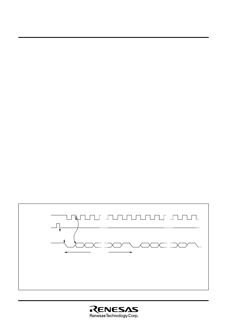
Fig. 21 Continuous transmission operation of UART serial I/O
[Baud Rate Generator] BRG
The baud rate generator determines the baud rate for serial transfer.
The baud rate generator divides the frequency of the count source
by 1/(n + 1), where n is the value written to the baud rate generator.
TSC=0
TBE=1
TBE=0
ST
D
0
D
1
SP
D
0
D
1
ST
SP
ST
1 :
When the serial I/O1 mode selection bit (b7, b6) is “10”, the transmit enable bit is “1”, and continuous transmit valid bit is “1”, writing on the
transmit buffer initiates continuous transmission of the same data.
2 :
Select 0 for continuous transmit valid bit to stop continuous transmission.
The T
X
D pin will stop at high level after completing transmission of 1 byte.
3 :
If the transmit buffer contents are rewritten during a continuous transmission, transmission of the rewritten data will be started after
completing transmission of 1 byte.
Notes
1 Start Bit
7 or 8 Data Bit
1 or 0 Parity Bit
1 or 2 Stop Bit
Transmit/Receive Clock
Transmit Buffer Register
Write Signal
Serial Output T
X
D
相關(guān)PDF資料 |
PDF描述 |
|---|---|
| 754080 | 250mA CMOS LDO, lsupply 1uA and 2% Vout Accuracy, -40C to +125C, 3-SOT-23, T/R |
| 8525X12 | SCHRAUBE LINSE SCHLITZ M2.5 12MM Inhalt pro Packung: 100 Stk. |
| 8525X16 | SCHRAUBE LINSE SCHLITZ M2.5 16MM Inhalt pro Packung: 100 Stk. |
| 8525X6 | SCHRAUBE LINSE SCHLITZ M2.5 6MM Inhalt pro Packung: 100 Stk. |
| 852X12 | SCHRAUBE LINSE SCHLITZ M2 12MM Inhalt pro Packung: 100 Stk. |
相關(guān)代理商/技術(shù)參數(shù) |
參數(shù)描述 |
|---|---|
| 75360 | 功能描述:BIT MICRO HEX SYST4 9/64" 28MM RoHS:否 類別:工具 >> 螺釘和螺母驅(qū)動(dòng)器 - 刀片和位 系列:系統(tǒng) 4 標(biāo)準(zhǔn)包裝:1 系列:TorqueVario™ 類型:十字槽刀片 尺寸:#2 長(zhǎng)度:7.48"(190mm) 特點(diǎn):絕緣達(dá) 10,000V 重量:0.07 磅(31.75g) |
| 75360-0033 | 制造商:MOLEX 功能描述:GBX 5 PAIR DAUGHTERCARD A |
| 753-602 | 制造商:WAGO Innovative Connections 功能描述:24V DC Power Supply |
| 753603 | 制造商:TE CONNECTIVITY 功能描述:BNC CONN AMP 制造商:Yokogawa Electric Corporation 功能描述:POCKET DMM, YOKOGAWA, YOKOGA |
| 753-603 | 制造商:WAGO Innovative Connections 功能描述:Potential Multiplication Module |
發(fā)布緊急采購(gòu),3分鐘左右您將得到回復(fù)。