- 您現(xiàn)在的位置:買賣IC網(wǎng) > PDF目錄68811 > 71M6532F-IGTR/F (MAXIM INTEGRATED PRODUCTS INC) 1-CHANNEL POWER SUPPLY MANAGEMENT CKT, PQFP100 PDF資料下載
參數(shù)資料
| 型號(hào): | 71M6532F-IGTR/F |
| 廠商: | MAXIM INTEGRATED PRODUCTS INC |
| 元件分類: | 電源管理 |
| 英文描述: | 1-CHANNEL POWER SUPPLY MANAGEMENT CKT, PQFP100 |
| 封裝: | LEAD FREE, LQFP-100 |
| 文件頁數(shù): | 43/120頁 |
| 文件大?。?/td> | 2477K |
| 代理商: | 71M6532F-IGTR/F |
第1頁第2頁第3頁第4頁第5頁第6頁第7頁第8頁第9頁第10頁第11頁第12頁第13頁第14頁第15頁第16頁第17頁第18頁第19頁第20頁第21頁第22頁第23頁第24頁第25頁第26頁第27頁第28頁第29頁第30頁第31頁第32頁第33頁第34頁第35頁第36頁第37頁第38頁第39頁第40頁第41頁第42頁當(dāng)前第43頁第44頁第45頁第46頁第47頁第48頁第49頁第50頁第51頁第52頁第53頁第54頁第55頁第56頁第57頁第58頁第59頁第60頁第61頁第62頁第63頁第64頁第65頁第66頁第67頁第68頁第69頁第70頁第71頁第72頁第73頁第74頁第75頁第76頁第77頁第78頁第79頁第80頁第81頁第82頁第83頁第84頁第85頁第86頁第87頁第88頁第89頁第90頁第91頁第92頁第93頁第94頁第95頁第96頁第97頁第98頁第99頁第100頁第101頁第102頁第103頁第104頁第105頁第106頁第107頁第108頁第109頁第110頁第111頁第112頁第113頁第114頁第115頁第116頁第117頁第118頁第119頁第120頁
FDS 6531/6532 005
Data Sheet 71M6531D/F-71M6532D/F
v1.3
2005-2010 TERIDIAN Semiconductor Corporation
29
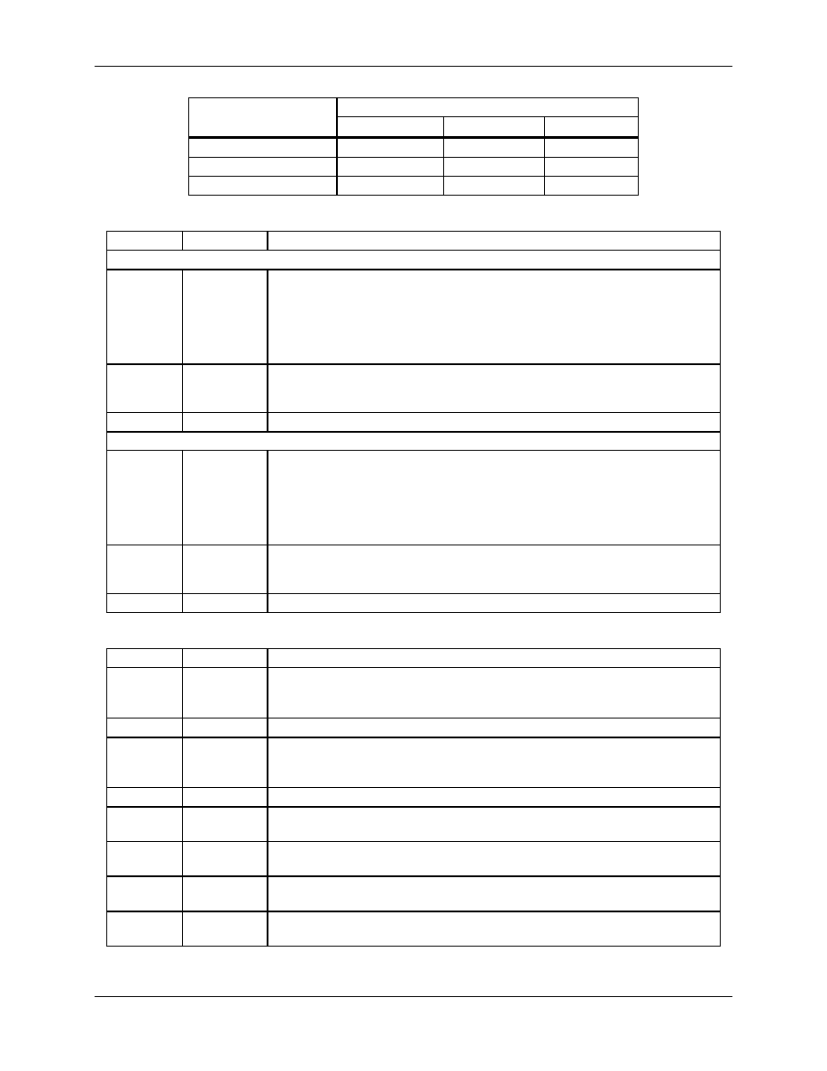
Table 21: Allowed Timer/Counter Mode Combinations
Timer 1
Mode 0
Mode 1
Mode 2
Timer 0 - mode 0
Yes
Timer 0 - mode 1
Yes
Timer 0 - mode 2
Not allowed
Yes
Table 22: TMOD Register Bit Description (SFR 0x89)
Bit
Symbol
Function
Timer/Counter 1:
TMOD[7]
Gate
If TMOD[7] is set, external input signal control is enabled for Counter 0.
external gate control. The TR1 bit in the TCON register (SFR 0x88) must
also be set in order for Counter 1 to increment.
With these settings Counter 1 is incremented on every falling edge of the
logic signal applied to one or more of the interrupt sources controlled by
the DI_RBP, DIO_R1, … DIO_RXX registers.
TMOD[6]
C/T
Selects timer or counter operation. When set to 1, a counter operation is
performed. When cleared to 0, the corresponding register will function as a
timer.
TMOD[5:4]
M1:M0
Selects the mode for Timer/Counter 1 as shown in Table 20.
Timer/Counter 0:
TMOD[3]
Gate
If TMOD[3] is set, external input signal control is enabled for Counter 0.
external gate control. The TR0 bit in the TCON register (SFR 0x88) must
also be set in order for Counter 0 to increment.
With these settings Counter 0 is incremented on every falling edge of the
logic signal applied to one or more of the interrupt sources controlled by
the DI_RBP, DIO_R1, … DIO_RXX registers.
TMOD[2]
C/T
Selects timer or counter operation. When set to 1, a counter operation is
performed. When cleared to 0, the corresponding register will function as
a timer.
TMOD[1:0]
M1:M0
Selects the mode for Timer/Counter 0, as shown in Table 20.
Table 23: The TCON Register Bit Functions (SFR 0x88)
Bit
Symbol
Function
TCON[7]
TF1
The Timer 1 overflow flag is set by hardware when Timer 1 overflows.
This flag can be cleared by software and is automatically cleared when an
interrupt is processed.
TCON[6]
TR1
Timer 1 run control bit. If cleared, Timer 1 stops.
TCON[5]
TF0
Timer 0 overflow flag set by hardware when Timer 0 overflows. This flag
can be cleared by software and is automatically cleared when an interrupt
is processed.
TCON[4]
TR0
Timer 0 Run control bit. If cleared, Timer 0 stops.
TCON[3]
IE1
Interrupt 1 edge flag is set by hardware when the falling edge on external
pin int1 is observed. Cleared when an interrupt is processed.
TCON[2]
IT1
Interrupt 1 type control bit. Selects either the falling edge or low level on
input pin to cause an interrupt.
TCON[1]
IE0
Interrupt 0 edge flag is set by hardware when the falling edge on external
pin int0 is observed. Cleared when an interrupt is processed.
TCON[0]
IT0
Interrupt 0 type control bit. Selects either the falling edge or low level on
input pin to cause interrupt.
相關(guān)PDF資料 |
PDF描述 |
|---|---|
| 71M6534-IGT/F | SPECIALTY ANALOG CIRCUIT, PQFP120 |
| 71M6534H-IGTR/F | SPECIALTY ANALOG CIRCUIT, PQFP120 |
| 71M6533H-IGTR/F | SPECIALTY ANALOG CIRCUIT, PQFP100 |
| 71M6534-IGTR/F | SPECIALTY ANALOG CIRCUIT, PQFP120 |
| 71M6534H-IGT/F | SPECIALTY ANALOG CIRCUIT, PQFP120 |
相關(guān)代理商/技術(shù)參數(shù) |
參數(shù)描述 |
|---|---|
| 71M6533 | 制造商:TERIDIAN 制造商全稱:TERIDIAN 功能描述:Energy Meter IC |
| 71M6533-DB | 功能描述:開發(fā)板和工具包 - 8051 71M6533 Demo Brd RoHS:否 制造商:Silicon Labs 產(chǎn)品:Development Kits 工具用于評(píng)估:C8051F960, Si7005 核心: 接口類型:USB 工作電源電壓: |
| 71M6533G | 制造商:MAXIM 制造商全稱:Maxim Integrated Products 功能描述:Exceeds IEC 62053/ANSI C12.20 Standards |
| 71M6533G-IGTR/F | 功能描述:計(jì)量片上系統(tǒng) - SoC AC Power Monitoring SoC-Programd RoHS:否 制造商:Maxim Integrated 核心:80515 MPU 處理器系列:71M6511 類型:Metering SoC 最大時(shí)鐘頻率:70 Hz 程序存儲(chǔ)器大小:64 KB 數(shù)據(jù) RAM 大小:7 KB 接口類型:UART 可編程輸入/輸出端數(shù)量:12 片上 ADC: 安裝風(fēng)格:SMD/SMT 封裝 / 箱體:LQFP-64 封裝:Reel |
| 71M6533H | 制造商:TERIDIAN 制造商全稱:TERIDIAN 功能描述:Energy Meter IC |
發(fā)布緊急采購,3分鐘左右您將得到回復(fù)。