- 您現(xiàn)在的位置:買賣IC網(wǎng) > PDF目錄157280 > 5962G9855201QXX 32-BIT, 12 MHz, RISC MICROCONTROLLER, CPGA144 PDF資料下載
參數(shù)資料
| 型號: | 5962G9855201QXX |
| 元件分類: | 微控制器/微處理器 |
| 英文描述: | 32-BIT, 12 MHz, RISC MICROCONTROLLER, CPGA144 |
| 封裝: | CERAMIC, PGA-144 |
| 文件頁數(shù): | 30/64頁 |
| 文件大?。?/td> | 1464K |
| 代理商: | 5962G9855201QXX |
第1頁第2頁第3頁第4頁第5頁第6頁第7頁第8頁第9頁第10頁第11頁第12頁第13頁第14頁第15頁第16頁第17頁第18頁第19頁第20頁第21頁第22頁第23頁第24頁第25頁第26頁第27頁第28頁第29頁當(dāng)前第30頁第31頁第32頁第33頁第34頁第35頁第36頁第37頁第38頁第39頁第40頁第41頁第42頁第43頁第44頁第45頁第46頁第47頁第48頁第49頁第50頁第51頁第52頁第53頁第54頁第55頁第56頁第57頁第58頁第59頁第60頁第61頁第62頁第63頁第64頁
36
Special Purpose Data Registers
In addition to the 20 general purpose data registers, the
UT69R000 has three special purpose data registers: (1) The
ACCUMULATOR (ACC); (2) the Stack Pointer (SP); and (3)
the Instruction Counter Save Register (ICS).
The Accumulator (ACC) is a 32-bit register used only with
multiply, divide, extended shift, Load Register from
Instruction memory (LRI), and Store Register to Instruction
memory (STRI) instructions. For multiply instructions, the
ACC retains the most significant half of the product, and for
divide instructions, the ACC retains the remainder. For LRI
and STRI instructions, the ACC contains the instruction
memory pointer. Note that the ACC can be used as a general
purpose register for most operations.
The Stack Pointer (SP) is a 16-bit register usable only with POP
and PUSH instructions.
The Instruction Counter Save (ICS) register is a 20-bit register
used during calls, jumps, and interrupts.
Register Notation
The UT69R000’s instruction descriptions contain a definition
of the Register Transfer Language (RTL) that the Assembler
uses to describe how the instructions operate. The RTL
description of the UT69R000’s internal registers is as follows:
RSn
-- Source Register where n specifies the
register number.
RDn -- Destination Register where n specifies the
register number.
XRSn -- Long-Data Source Register where n specifies the
register number.
XRDn -- Long-Data Destination Register where n specifies
the register number.
IC
-- Instruction Counter
SP
-- Stack Pointer
ACC -- 32 bit Accumulator
ICS
-- Instruction Counter Store Register
@RSn-- Data Register Indirect where n specifies the
register number
@SP -- Stack Pointer Indirect
#
-- Immediate Data
@#
-- Immediate Data Indirect
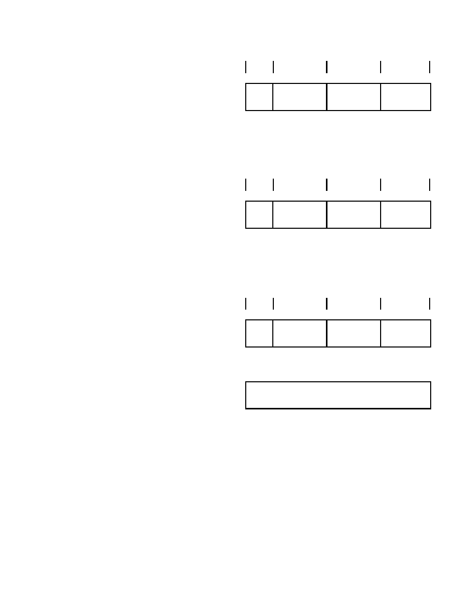
9.2 Instruction Formats
The UT69R000 has three instruction formats (figure 32): (1)
Register-to-Register; (2) Register-to-Short Immediate; and (3)
Register-to-Immediate.
All the UT69R000’s instructions are either word (16-bit) or
long-word (32-bit) in length. The only time the UT69R000 uses
the long-word instruction format is for the Immediate Source
Operand Address Mode.
The bits in the instructions are defined as follows:
M: Instruction Mode Bit. When M = 1, the UT69R000
interprets the Instruction Source field as a five-bit literal
value. If M = 0, the UT69R000 uses the Instruction Source
field to specify the source register for the instruction.
Opcode: This field is the five-bit opcode the UT69R000
uses to decode the instruction into a machine operation.
0
4
5
9
10
14
15
Figure 31b. Register to-Short Immediate
0
4
5
9
10
14
15
Figure 31a. Register to-Register Instruction
Figure 31c. Register Immediate Instruction Format
MSB
LSB
MODE
OPCODE
DESTINATION
SOURCE
0
XXXXX
RD
RS
MODE
OPCODE
DESTINATION
SOURCE
MSB
LSB
1
XXXXX
RD
IMMEDIATE
MODE
MSB
OPCODE
DESTINATION
SOURCE
LSB
0
XXXXX
RD
11111
0
4
5
9
10
14
15
16-Bit Immediate Data
15
0
MSB
LSB
Instruction Format
相關(guān)PDF資料 |
PDF描述 |
|---|---|
| 5962G9855202VXA | 32-BIT, 16 MHz, RISC MICROCONTROLLER, CPGA144 |
| 5962G9855202VXX | 32-BIT, 16 MHz, RISC MICROCONTROLLER, CPGA144 |
| 5962H9855201VXC | 32-BIT, 12 MHz, RISC MICROCONTROLLER, CPGA144 |
| 5962H9855202QXX | 32-BIT, 16 MHz, RISC MICROCONTROLLER, CPGA144 |
| 5962H9855202VXX | 32-BIT, 16 MHz, RISC MICROCONTROLLER, CPGA144 |
相關(guān)代理商/技術(shù)參數(shù) |
參數(shù)描述 |
|---|---|
| 5962H94A0305QXC | 制造商: 功能描述: 制造商:undefined 功能描述: |
| 5962H9853701 | 制造商: 功能描述: 制造商:undefined 功能描述: |
| 5962L0051502VHA | 制造商:Analog Devices 功能描述:AEROSPACE 7NS SINGLE COMPARATOR - Trays |
| 5962L0052401VGA | 功能描述:校驗器 IC RoHS:否 制造商:STMicroelectronics 產(chǎn)品: 比較器類型: 通道數(shù)量: 輸出類型:Push-Pull 電源電壓-最大:5.5 V 電源電壓-最小:1.1 V 補(bǔ)償電壓(最大值):6 mV 電源電流(最大值):1350 nA 響應(yīng)時間: 最大工作溫度:+ 125 C 安裝風(fēng)格:SMD/SMT 封裝 / 箱體:SC-70-5 封裝:Reel |
| 5962L0052401VHA | 功能描述:校驗器 IC RoHS:否 制造商:STMicroelectronics 產(chǎn)品: 比較器類型: 通道數(shù)量: 輸出類型:Push-Pull 電源電壓-最大:5.5 V 電源電壓-最小:1.1 V 補(bǔ)償電壓(最大值):6 mV 電源電流(最大值):1350 nA 響應(yīng)時間: 最大工作溫度:+ 125 C 安裝風(fēng)格:SMD/SMT 封裝 / 箱體:SC-70-5 封裝:Reel |
發(fā)布緊急采購,3分鐘左右您將得到回復(fù)。