- 您現(xiàn)在的位置:買賣IC網(wǎng) > PDF目錄1887 > 100-1221-3 (Bluetechnix)CORE MOD CM-BF537E 600MHZ CONN PDF資料下載
參數(shù)資料
| 型號: | 100-1221-3 |
| 廠商: | Bluetechnix |
| 文件頁數(shù): | 48/68頁 |
| 文件大小: | 0K |
| 描述: | CORE MOD CM-BF537E 600MHZ CONN |
| 標準包裝: | 1 |
| 模塊/板類型: | 核心模塊 |
| 其它名稱: | 100-1221 100-1221-ND |
第1頁第2頁第3頁第4頁第5頁第6頁第7頁第8頁第9頁第10頁第11頁第12頁第13頁第14頁第15頁第16頁第17頁第18頁第19頁第20頁第21頁第22頁第23頁第24頁第25頁第26頁第27頁第28頁第29頁第30頁第31頁第32頁第33頁第34頁第35頁第36頁第37頁第38頁第39頁第40頁第41頁第42頁第43頁第44頁第45頁第46頁第47頁當前第48頁第49頁第50頁第51頁第52頁第53頁第54頁第55頁第56頁第57頁第58頁第59頁第60頁第61頁第62頁第63頁第64頁第65頁第66頁第67頁第68頁

Rev. J
|
Page 52 of 68
|
February 2014
TEST CONDITIONS
All timing parameters appearing in this data sheet were
measured under the conditions described in this section.
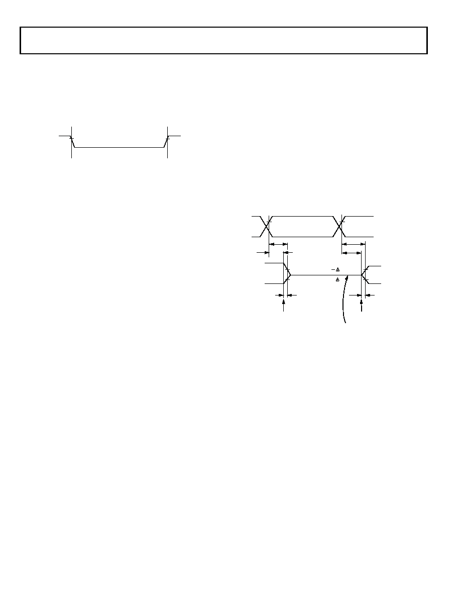
Figure 48 shows the measurement point for ac measurements
(other than output enable/disable). The measurement point is
VMEAS = VDDEXT/2.
Output Enable Time
Output pins are considered to be enabled when they have made
a transition from a high impedance state to the point when they
start driving. The output enable time tENA is the interval from
the point when a reference signal reaches a high or low voltage
level to the point when the output starts driving as shown in the
Output Enable/Disable diagram (Figure 49). The time tENA_MEA-
SURED is the interval from when the reference signal switches to
when the output voltage reaches 2.0 V (output high) or 1.0 V
(output low). Time tTRIP is the interval from when the output
starts driving to when the output reaches the 1.0 V or 2.0 V trip
voltage. Time tENA is calculated as shown in
the equation:
If multiple pins (such as the data bus) are enabled, the measure-
ment value is that of the first pin to start driving.
Output Disable Time
Output pins are considered to be disabled when they stop driv-
ing, go into a high impedance state, and start to decay from their
output high or low voltage. The time for the voltage on the bus
to decay by V is dependent on the capacitive load, CL, and the
load current, IL. This decay time can be approximated by
the equation:
The output disable time tDIS is the difference between tDIS_MEA-
the interval from when the reference signal switches to when the
output voltage decays V from the measured output-high or
output-low voltage. The time tDECAY is calculated with the test
loads CL and IL, and with V equal to 0.5 V.
Example System Hold Time Calculation
To determine the data output hold time in a particular system,
first calculate tDECAY using the equation given above. Choose V
to be the difference between the processor’s output voltage and
the input threshold for the device requiring the hold time. A
typical V is 0.4 V. CL is the total bus capacitance (per data line),
and IL is the total leakage or three-state current (per data line).
The hold time is tDECAY plus the minimum disable time (for
example, tDSDAT for an SDRAM write cycle).
Figure 48. Voltage Reference Levels for AC Measurements (Except
Output Enable/Disable)
INPUT
OR
OUTPUT
VMEAS
tENA
tENA_MEASURED tTRIP
–
=
Figure 49. Output Enable/Disable
tDECAY
CL V
I
L
=
REFERENCE
SIGNAL
tDIS
OUTPUT STARTS DRIVING
VOH (MEASURED)
V
VOL (MEASURED) + V
tDIS_MEASURED
VOH
(MEASURED)
VOL
(MEASURED)
VTRIP(HIGH)
VOH(MEASURED)
VOL(MEASURED)
HIGH IMPEDANCE STATE
OUTPUT STOPS DRIVING
tENA
tDECAY
tENA_MEASURED
tTRIP
VTRIP(LOW)
相關(guān)PDF資料 |
PDF描述 |
|---|---|
| 100-1225-1 | CORE MOD TCM-BF537 500MHZ CONN |
| 100-1254-2 | MODULE BF527-C-C-Q50S64F8 |
| 101-0303 | SMARTSCREEN OP7100 DISPLAY |
| 101-0383 | MODULE RABBITCORE RCM2020 |
| 101-0435 | MODULE RABBITCORE RCM2110 |
相關(guān)代理商/技術(shù)參數(shù) |
參數(shù)描述 |
|---|---|
| 1001224 | 功能描述:防靜電控制產(chǎn)品 12X24 PKG/100 RoHS:否 制造商:3M Electronic Specialty 產(chǎn)品:Air Ionizers 類型:Mini 顏色: 大小:4.5 in x 3.3 in x 2 in |
| 1001225 | 功能描述:防靜電控制產(chǎn)品 12X25 PKG/100 RoHS:否 制造商:3M Electronic Specialty 產(chǎn)品:Air Ionizers 類型:Mini 顏色: 大小:4.5 in x 3.3 in x 2 in |
| 100-1225-1 | 功能描述:CORE MOD TCM-BF537 500MHZ CONN RoHS:是 類別:集成電路 (IC) >> 嵌入式 - 微控制器或微處理器模塊 系列:- 產(chǎn)品目錄繪圖:DLP-245SY-G 標準包裝:1 系列:USB 模塊/板類型:開發(fā)板 適用于相關(guān)產(chǎn)品:USB 其它名稱:813-1006 |
| 10-01-2259 | 功能描述:集管和線殼 KK 100 Housing Crimp Crimp Std 25 Ckt RoHS:否 產(chǎn)品種類:1.0MM Rectangular Connectors 產(chǎn)品類型:Headers - Pin Strip 系列:DF50 觸點類型:Pin (Male) 節(jié)距:1 mm 位置/觸點數(shù)量:16 排數(shù):1 安裝風格:SMD/SMT 安裝角:Right 端接類型:Solder 外殼材料:Liquid Crystal Polymer (LCP) 觸點材料:Brass 觸點電鍍:Gold 制造商:Hirose Connector |
| 100122A | 制造商:未知廠家 制造商全稱:未知廠家 功能描述:Nine Bit Buffer |
發(fā)布緊急采購,3分鐘左右您將得到回復(fù)。