- 您現(xiàn)在的位置:買賣IC網(wǎng) > PDF目錄372876 > XC95144XLSERIES High Performance CPLD PDF資料下載
參數(shù)資料
| 型號(hào): | XC95144XLSERIES |
| 英文描述: | High Performance CPLD |
| 中文描述: | 高性能的CPLD |
| 文件頁數(shù): | 3/9頁 |
| 文件大小: | 84K |
| 代理商: | XC95144XLSERIES |
November 13, 1998 (Version 1.2)
3
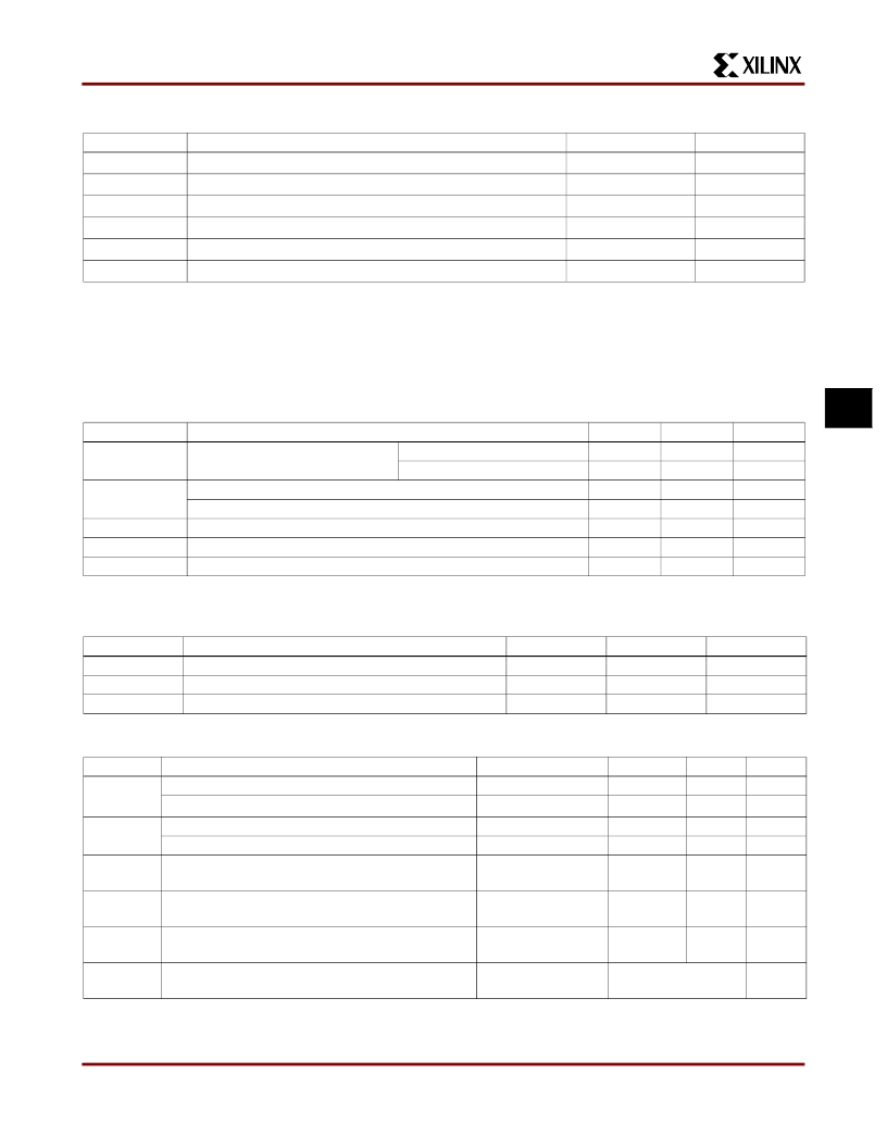
Absolute Maximum Ratings
Recommended Operation Conditions
Quality and Reliability Characteristics
DC Characteristics Over Recommended Operating Conditions
Symbol
V
CC
V
IN
V
TS
T
STG
T
SOL
T
J
Note 1: Maximum DC undershoot below GND must be limited to either 0.5 V or 10 mA, whichever is easier to achieve. During
transitions, the device pins may undershoot to -2.0 V or overshoot to +7.0 V, provided this over- or undershoot lasts less
than 10 ns and with the forcing current being limited to 200 mA.
Note 2: Stresses beyond those listed under Absolute Maximum Ratings may cause permanent damage to the device. These are stress
ratings only, and functional operation of the device at these or any other conditions beyond those listed under Operating
Conditions is not implied. Exposure to Absolute Maximum Ratings conditions for extended periods of time may affect device
reliability.
Description
Value
-0.5 to 4.0
-0.5 to 5.5
-0.5 to 5.5
-65 to +150
+260
+150
Units
V
V
V
o
C
o
C
o
C
Supply voltage relative to GND
Input voltage relative to GND (Note 1)
Voltage applied to 3-state output (Note 1)
Storage temperature (ambient)
Maximum soldering temperature (10s @ 1/16 in. = 1.5 mm)
Junction temperature
Symbol
V
CCINT
Parameter
Min
3.0
3.0
3.0
2.3
0
2.0
0
Max
3.6
3.6
3.6
2.7
0.80
5.5
V
CCIO
Units
V
V
V
V
V
V
V
Supply voltage for internal logic
and input buffers
Supply voltage for output drivers for 3.3 V operation
Supply voltage for output drivers for 2.5 V operation
Low-level input voltage
High-level input voltage
Output voltage
Commercial T
A
= 0
o
C to 70
o
C
Industrial T
A
= -40
o
C to +85
o
C
V
CCIO
V
IL
V
IH
V
O
Symbol
t
DR
N
PE
V
ESD
Parameter
Min
20
10,000
2,000
Max
-
-
-
Units
Years
Cycles
Volts
Data Retention
Program/Erase Cycles (Endurance)
Electrostatic Discharge (ESD)
Symbol
V
OH
Parameter
Test Conditions
I
OH
= -4.0 mA
I
OH
= -500
μ
A
I
OL
= 8.0 mA
I
OL
= 500
μ
A
V
CC
= Max
V
IN
= GND or V
CC
V
CC
= Max
V
IN
= GND or V
CC
V
IN
= GND
f = 1.0 MHz
V
I
= GND, No load
f = 1.0 MHz
Min
2.4
Max
Units
V
V
V
V
μ
A
Output high voltage for 3.3 V outputs
Output high voltage for 2.5 V outputs
Output low voltage for 3.3 V outputs
Output low voltage for 2.5 V outputs
Input leakage current
90% V
CCIO
V
OL
0.4
0.4
± 10.0
I
IL
I
IH
I/O high-Z leakage current
± 10.0
μ
A
C
IN
I/O capacitance
10.0
pF
I
CC
Operating Supply Current
(low power mode, active)
45
ma
相關(guān)PDF資料 |
PDF描述 |
|---|---|
| XC95288-10BG352C | Flash Complex PLD |
| XC95288-10HQ208C | Flash Complex PLD |
| XC95288-15BG352C | Flash Complex PLD |
| XC95288-15BG352I | Flash Complex PLD |
| XC95288-15HQ208C | Flash Complex PLD |
相關(guān)代理商/技術(shù)參數(shù) |
參數(shù)描述 |
|---|---|
| XC95144XLTQ11C | 制造商:XILINX 功能描述:NEW |
| XC95144XV | 制造商:XILINX 制造商全稱:XILINX 功能描述:High-Performance CPLD |
| XC95144XV_07 | 制造商:XILINX 制造商全稱:XILINX 功能描述:High-Performance CPLD |
| XC95144XV-4CS144C | 制造商:XILINX 制造商全稱:XILINX 功能描述:High-Performance CPLD |
| XC95144XV-4CS144I | 制造商:XILINX 制造商全稱:XILINX 功能描述:High-Performance CPLD |
發(fā)布緊急采購,3分鐘左右您將得到回復(fù)。